Hi, I am trying to run servos using PCA9685 and at the same time get another i2c to run MPU6050, can I do that? Thanks
IIRC, there are I2C expanders, I am pretty sure we had a discussion here recently. Again, IIRC you only need 3 pins on the MPU but can control 16, or 32, or possibly more individual devices. A quick google tells me MCP23017 gives you 16 channels.
First computer 1959. Retired from my own computer company 2004.
Hardware - Expert in 1401, and 360, fairly knowledge in PC plus numerous MPU's and MCU's
Major Languages - Machine language, 360 Macro Assembler, Intel Assembler, PL/I and PL1, Pascal, Basic, C plus numerous job control and scripting languages.
Sure you can learn to be a programmer, it will take the same amount of time for me to learn to be a Doctor.
Hi @wolfbane,
I haven't used the devices you mention, but I just had a two minute lookat the data sheets.
The MPU6050 seems to respond to a choice of two different addresses ..
from https://invensense.tdk.com/wp-content/uploads/2015/02/MPU-6000-Datasheet1.pdf
I read:
The slave address of the MPU-60X0 is b110100X which is 7 bits long. The LSB bit of the 7 bit address is determined by the logic level on pin AD0. This allows two MPU-60X0s to be connected to the same I2C bus.
When used in this configuration, the address of the one of the devices should be b1101000 (pin AD0 is logic low) and the address of the other should be b1101001 (pin AD0 is logic high).
The PCA9685 is more flexible, albeit with some small print too check out in case there is a clash .. from https://www.nxp.com/docs/en/data-sheet/PCA9685.pdf
I see:
7.1 Device addresses
Following a START condition, the bus master must output the address of the slave it is
accessing.
There are a maximum of 64 possible programmable addresses using the 6 hardware
address pins. Two of these addresses, Software Reset and LED All Call, cannot be used
because their default power-up state is ON, leaving a maximum of 62 addresses. Using
other reserved addresses, as well as any other subcall address, will reduce the total
number of possible addresses even further.
I haven't read all the small print, including whether the PC9685 reserved addresses overlap the MPU6050 choices, etc., but with a little luck and care, they mght well be happy to share the same bus.
Suggest you have a read of the details to check. Don't add extra stuff if it not actually needed!
Best wishes, Dave
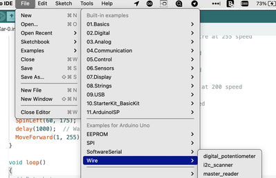
@wolfsbane FYI @davee Don't forget you can use the Example sketch "i2c_scanner" to 'read' the I2C address that any I2C device is configured for. You can even run this on several at the same time if you want.
First computer 1959. Retired from my own computer company 2004.
Hardware - Expert in 1401, and 360, fairly knowledge in PC plus numerous MPU's and MCU's
Major Languages - Machine language, 360 Macro Assembler, Intel Assembler, PL/I and PL1, Pascal, Basic, C plus numerous job control and scripting languages.
Sure you can learn to be a programmer, it will take the same amount of time for me to learn to be a Doctor.
Hi @zander @wolfbane
Re: Don't forget you can use the Example sketch "i2c_scanner" ...
That is a good idea Ron ... I should add I only looked at the data sheet for the bare chips ... you may have them already soldered to small boards and need to understand how the address pins are 'hardwired' or broughtg out to the external pin connections.
My point is I2C was invented (by Philips) as very simple way of allowing the chips in a colour TV to communicate using just two wires (and perhaps a couple of resistors), and hence they were meant to all be on the same bus. For cheapness, and because Philips were designing the whole TV chip set, each chip was internally hardwired to its own address .. or sometimes just one pin would be external to give a choice of two addresses .. bearing in mind, pins are one of the most expensive part of small chips and the colour TV market was very cut-throat on price.
The MPU6050 seems to have followed that principle.
The PCA9685 has been designed for a wider range of applications, and has more external address pins, so it can be 'moved around' and (I think) several PCA9685s can be controlled on the same bus. However there are some rules about two or more 'reserved' addresses .. I didn't read the details, but the data sheet looked pretty starightforward at first glance.
Good luck! Dave

