Hi Guys,
I want to use the ESP32 to sense if a 12v 6amp DC pump turns on (to monitor pump cycles)
How should I handle the DC motor coil induced voltage backlash when the motor stops, into my ESP32 ?
I researched and came up with some maybe options, looking for suggestions please.
1. 2 x Resistor Voltage Divide the input from 12v down to below 3.3 - with the output going to my ESP32 pin. This option does not appear to have much protection from the DC motor coil voltage spike.... I would need some help here, maybe I would want a diode somewhere?
2. Level shifter - The boards I see on the web all require some input voltage, and are always on - this eats power. I'm looking for extremely low power usage here. So this does not appear to be a good choice.
3. Opto isolated circuit - looking for help with the circuit for this please, DC 12v @ 6amp to ESP32 input
4. Maybe a buck converter?
Thanks
Genki
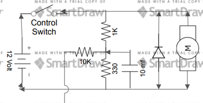
Obviously the optical isolation will give you the best protection but looking at what is at risk ($5 circuit board) compared to the additional cost and complication I'm not sure it's the best decision. The simplest rout is the voltage divider with a 1K and 330 ohm with a 10 mf capacitor across the 330 resister is simple, low cost and relative safe. For additional safety you could replace the capacitor with a reverse polarity diode and add a 3 volt zener diode across the 330 resistor. If you don't have a zener diode you could stack 5 silicon diodes (each with a .6V drop) end to end in the same location.
Andre Spiess (I think I spelled that right) just did a video on current sensors. Maybe what you want to do is detect when there is current in the line instead of trying to measure the voltage.
Pat Wicker (Portland, OR, USA)
Thanks for the responses guys. I will definitely take a look at that guy with the Swiss accents latest.
Ruplicator, I'm still new to this electronics game, is there anywhere that I could see a schematic for this type of Voltage divider with the safety features added, to help me build it ?
Thanks again
Genki
Hi Ruplicator,
Thank you very much, that is incredibly helpful of you and I appreciate it.
I will give it a go and report back on how it works out.
Thanks
Genki
Please don't forget to test the voltages before you connect to you ESP32. It is easy to miss-read the values on components or make wiring errors. Just set up the circuit without connecting the ESP32 and confirm with a volt meter the input that would normally feed it is in the correct range and polarity in both motor on and off conditions. Also don't forget that the negative ground of the motor circuit must be connected to the signal ground of the ESP32.
Hi, One thing I would like to add,
You can protect against DC spikes by putting a general purpose diode across the DC input to the motor.
This will limit the DC spike to one diode drop. Approx 0.7Vdc above Vcc.
Hope this helps,
Regards
--->The BLM<---

