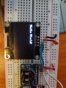
@fishbone There is something I don't understand, I looked up that display on amazon and the picture of the back shows I2C address jumpers of 78 and 7A. I have one of those so I will try it tomorrow. Have a look at the back of your OLED board, if it says 78 and 7A then plug that number into the sketch (whichever jumper is enabled, usually 78)
First computer 1959. Retired from my own computer company 2004.
Hardware - Expert in 1401, and 360, fairly knowledge in PC plus numerous MPU's and MCU's
Major Languages - Machine language, 360 Macro Assembler, Intel Assembler, PL/I and PL1, Pascal, Basic, C plus numerous job control and scripting languages.
Sure you can learn to be a programmer, it will take the same amount of time for me to learn to be a Doctor.
@fishbone I ordered some of these https://amz.run/6OE0 and will see how I make out.
First computer 1959. Retired from my own computer company 2004.
Hardware - Expert in 1401, and 360, fairly knowledge in PC plus numerous MPU's and MCU's
Major Languages - Machine language, 360 Macro Assembler, Intel Assembler, PL/I and PL1, Pascal, Basic, C plus numerous job control and scripting languages.
Sure you can learn to be a programmer, it will take the same amount of time for me to learn to be a Doctor.
@zander Check this out!
You ready for this? I went through a bunch of forums and found one where a guy had a garbled screen just like mine. He bought his from a website selling them as SSD1306 but they were actually SSD1106...so I installed the library U8G2 and selected SSD1106 and it fired right up.
I went back and reported the seller on Amazon since his description clearly stated SSD1306....a$$hole.
Anyway...sorry to waste the time of all of the good people here. It is just so frustrating to start a new hobby and have people mess with you - This is 8 hrs I wont be getting back!
Mark
@fishbone That explains it then cuz the 1306 I just ordered is at address 0x78 and 0x7A and I couldn't understand why. Also I just looked at a few 1106 modules on Amazon and they all have 0x78/0x7A as the address. Also they are listed as 1.3"
First computer 1959. Retired from my own computer company 2004.
Hardware - Expert in 1401, and 360, fairly knowledge in PC plus numerous MPU's and MCU's
Major Languages - Machine language, 360 Macro Assembler, Intel Assembler, PL/I and PL1, Pascal, Basic, C plus numerous job control and scripting languages.
Sure you can learn to be a programmer, it will take the same amount of time for me to learn to be a Doctor.
@fishbone I did a little more digging around the addressing differences and long story short 0x3C and 0x78 are sort of the same. Here is the long story
One of life’s most puzzling puzzles:
Is the address 0x78 or is it 0x3C?Answer: Both of the above, depending on your Point of View.
Data sheets almost always give the I2C device address as a 7-bit number. For these devices, the 7-bit device address depends on the jumper setting, and is either
Binary 011 1100 (Hexadecimal 0x3C)
orBinary 011 1101 (Hexadecimal 0x3D)
I note that many of the Data Sheets only give 7-bit binary values and leaves the user to figure out what the Hex values are, depending on how they may be used in an application’s software routines.
Here’s an excerpt from the Data Sheet for an SSD1306:
Either “0111100” or “0111101”, can be selected as the slave address of SSD1306.
Consider the first configuration:
Now on the I2C bus, the first byte after putting the I2C “Start” condition on the bus goes like this:
For beginning a “Write” transaction, the device address is shifted left one bit, giving binary 0111 1000 (hexadecimal 0x78). For a “Write” transaction, the LSB (Least Significant Bit) is left as ‘0’. For a “Read” transaction the LSB is set to ‘1’.
Just about all of the professional (and almost-professional) software libraries that I have used — Circuit Python, Micropython, and lots (and lots) of C/C++ libraries for Raspberry Pi and approximately a gazillion Microchip PIC processors— use the 7-bit address when calling I2C libraries.
On the other hand:
I have seen posts where individuals have written library routines that use 0x78 (binary 0111 1000) as the address parameter in the calling routine, and the library function sets the Least Significant Bit for reading.
Bottom line: If your I2C scan program shows 0x3C, it is consistent with the silkscreen 0x78 label. If you change your board to use the 0x7A position (8-bit binary 0111 1010), (and you did it right) you should see 0x3D as the I2C device address in your I2C scanner program.
First computer 1959. Retired from my own computer company 2004.
Hardware - Expert in 1401, and 360, fairly knowledge in PC plus numerous MPU's and MCU's
Major Languages - Machine language, 360 Macro Assembler, Intel Assembler, PL/I and PL1, Pascal, Basic, C plus numerous job control and scripting languages.
Sure you can learn to be a programmer, it will take the same amount of time for me to learn to be a Doctor.

