Hi all, hopefully this post will not be too long.
As mentioned in my intro I am a maker newbie. For my first project I picked the ESP32-CAM. Specifically an ESP32-CAM (AI-Thinker) using a AM312 PIR sensor. Ultimately I want the camera to detect motion and send the photo to a mobile app and start the camera streaming (I am a software dev in my day job). Eventually I plan on designing and 3d Printing a unit to house it. So a lot of fun work ahead of me.
I do not have much equipment yet, intend to build on that gradually.
I have an Arduino, a basic multimeter and basic soldering kit, some small breadboards, some proto-boards, wires and various basic components.
Currently I am unable to get the circuit working.
So far looks like I have killed 1x ESP32-CAM and 2x AM312 PIR sensors when using FTDI cards so now using ESP32-CAM MB. Keep telling myself the best way to learn is to fail 😀
I have tried using the DroneBotWorkshop sketch and after uploading the sketch using the ESP32-CAM MB the camera was continually taking images. I never got as far as the circuit building. Not sure why I had problems from the get go. https://dronebotworkshop.com/esp32-cam-microsd/#Motion-Activated_Camera
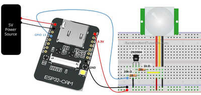
So then I tried the RandomNerd sketch - this takes the initial image but then the sensor does not ever trigger again. I followed the Fritzing diagram https://randomnerdtutorials.com/esp32-cam-pir-motion-detector-photo-capture/#comment-813010
I have tested the camera on it's own and that works. (Tested a sketch with timer delays.)
I have tested the PIR sensor on a simple led circuit and that works fine - has good detection.
My issue is getting them to work together. I am sure I am missing something really basic.
Hopefully someone can give some guidance.
My current setup is:
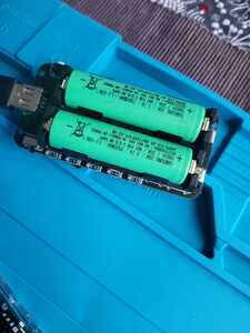
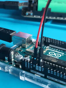
Power: 18650 battery shield with 2 batteries connected to Arduino Uno R3
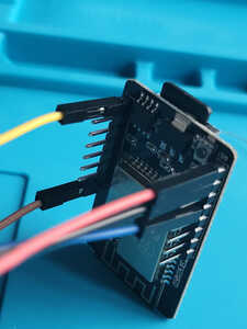
5v from Arduino to ESP32-CAM (AI-Thinker) then 3.5v to breadboard
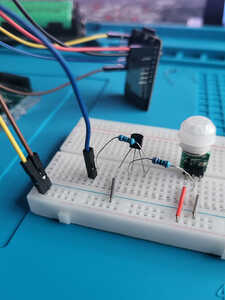
AM312 PIR sensor
1k & 10K resistors (blue ones ?)
NPN 2N3904 transistor
A few photos of setup
Thanks,
Darren
@cuznerdexter What exactly is not working? Have you modified the camera code to use a pin to take a picture? All the esp32 sketches I have used are web based so no pins, just buttons.
I am sure you know that you need to connect the output of the PIR to the into of the camera trigger. Not sure where you are going wrong.
First computer 1959. Retired from my own computer company 2004.
Hardware - Expert in 1401, and 360, fairly knowledge in PC plus numerous MPU's and MCU's
Major Languages - Machine language, 360 Macro Assembler, Intel Assembler, PL/I and PL1, Pascal, Basic, C plus numerous job control and scripting languages.
Sure you can learn to be a programmer, it will take the same amount of time for me to learn to be a Doctor.
I'm puzzled. You don't need a Uno and an ESP. You can connect the PIR to the ESP.
FTDI ? I have a cam board which came with a USB module plugged in so you just power the whole thing off a USB cable, then no chances of incorrect voltages. I've got FTDI type boards with a 5V/3V3 jumper, this could help you kill a 3V3 board if set to 5V. I think the USB module is available separately for very little money.
I think the PIR should work off 3v3 from the ESP so no need for resistors or transistor.
The randomnerd channel is one of the best, trust them.
I once walked past a sign on a wall "Experience is the best teacher, only the school fees are so high".
@hilldweller @zander thanks for the advice. As I am a newbie I am probably missing something real simple.
As far as I know I have copied the Fritzing schematic exactly.
I ordered the same parts used in the RandomNerds project, got them from AliExpress.
@zander I have not modified the RandomNerds sketch, I just uploaded it to the esp32-cam using the esp32-cam mb.
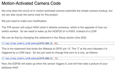
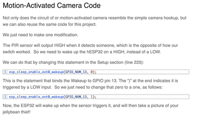
It connects the PIR Out to PIN 13.
esp_sleep_enable_ext0_wakeup(GPIO_NUM_13, 0);
It looks like the camera triggers, takes the initial photo, then goes into deep sleep, waiting for the sensor to trigger again it but the cam never gets notified by the sensor. I have tried multiple different resistor combinations but no success.
@hilldweller
I have a cam board which came with a USB module plugged in so you just power the whole thing off a USB cable
What board is this? do you have a link? The esp32-cam-mb is only used to upload the sketch.
The Arduino was used to temporarily connect the battery shield (by usb) to the esp32-cam, ultimately the battery will connect directly to the esp32-cam so the system can be located in my garden, front porch etc.
Thanks,
Darren
@cuznerdexter You have the MB board it looks like. I think the issue is that the code you reference with deep sleep is in the setup section so only runs once. That sketch has to be reworked an unknown amount
First computer 1959. Retired from my own computer company 2004.
Hardware - Expert in 1401, and 360, fairly knowledge in PC plus numerous MPU's and MCU's
Major Languages - Machine language, 360 Macro Assembler, Intel Assembler, PL/I and PL1, Pascal, Basic, C plus numerous job control and scripting languages.
Sure you can learn to be a programmer, it will take the same amount of time for me to learn to be a Doctor.
@cuznerdexter I think you missed reading one sentence, change the 0 to a 1 in
esp_sleep_enable_ext0_wakeup(GPIO_NUM_13, 0);
First computer 1959. Retired from my own computer company 2004.
Hardware - Expert in 1401, and 360, fairly knowledge in PC plus numerous MPU's and MCU's
Major Languages - Machine language, 360 Macro Assembler, Intel Assembler, PL/I and PL1, Pascal, Basic, C plus numerous job control and scripting languages.
Sure you can learn to be a programmer, it will take the same amount of time for me to learn to be a Doctor.
the code you reference with deep sleep is in the setup section so only runs once ..
Thanks. That makes sense to me. I am learning all about electronics from scratch, so still getting my head around voltages, resistors, transformers and stuff.
I was trusting that RandomNerds sketch would just work with modification and save me some hassle - guess not.
Hopefully I can rework the code and get this project started.
Thanks,
Darren
@cuznerdexter Sorry, that comment about setup was wrong, but the setting of 0 to 1 is correct
let us know when you test it so this topic can be closed
First computer 1959. Retired from my own computer company 2004.
Hardware - Expert in 1401, and 360, fairly knowledge in PC plus numerous MPU's and MCU's
Major Languages - Machine language, 360 Macro Assembler, Intel Assembler, PL/I and PL1, Pascal, Basic, C plus numerous job control and scripting languages.
Sure you can learn to be a programmer, it will take the same amount of time for me to learn to be a Doctor.
@cuznerdexter I was mistaken, just change the 0 to 1 in
esp_sleep_enable_ext0_wakeup(GPIO_NUM_13, 0);
as documented by Bill in his video/blog
First computer 1959. Retired from my own computer company 2004.
Hardware - Expert in 1401, and 360, fairly knowledge in PC plus numerous MPU's and MCU's
Major Languages - Machine language, 360 Macro Assembler, Intel Assembler, PL/I and PL1, Pascal, Basic, C plus numerous job control and scripting languages.
Sure you can learn to be a programmer, it will take the same amount of time for me to learn to be a Doctor.
ESP32Cam pair. This is with external aerial which buys you a greater range. Warning: some ESP32 boards have an on board aerial AND a connector, you sometime have to move a tiny zero ohm resister to connect to the external connector, it's not for the faint hearted. You can heat and remove the resistor and join the connector with a solder blob.
eBay item number:203826423743
How they sell them at this price is a mystery !
Hopefully I can rework the code and get this project started.
If you have two problems test them totally separately. In other words get the sleep/waken running with no camera code to confuse the issue. An LED plus resister and a jumper wire can test this. Then LED with the PIR. Then change to the camera.
Whenever it works, save under a new name, then easy to step back.
@hilldweller Not such a mystery, at $16.17 + $23.91 shipping vs Amazon at $15.73.
First computer 1959. Retired from my own computer company 2004.
Hardware - Expert in 1401, and 360, fairly knowledge in PC plus numerous MPU's and MCU's
Major Languages - Machine language, 360 Macro Assembler, Intel Assembler, PL/I and PL1, Pascal, Basic, C plus numerous job control and scripting languages.
Sure you can learn to be a programmer, it will take the same amount of time for me to learn to be a Doctor.
@hilldweller While divide and conquer is a time honored debugging technique, in this case, it was a case of user error, and failure to read and comprehend the documentation. Changing one parameter from 0 to 1 makes the sketch work.
First computer 1959. Retired from my own computer company 2004.
Hardware - Expert in 1401, and 360, fairly knowledge in PC plus numerous MPU's and MCU's
Major Languages - Machine language, 360 Macro Assembler, Intel Assembler, PL/I and PL1, Pascal, Basic, C plus numerous job control and scripting languages.
Sure you can learn to be a programmer, it will take the same amount of time for me to learn to be a Doctor.
@zander I have tried both of these solutions, multiple times now and previously with both Bill's sketches and RandomNerds.
Tried: esp_sleep_enable_ext0_wakeup(GPIO_NUM_13, 0); (PIR does not wake cam)
esp_sleep_enable_ext0_wakeup(GPIO_NUM_13, 1); (Cam takes photos continuously - even without the pir in the circuit)
@hilldweller I have already debugged using led's and no camera - circuit worked fine.
I have tested led with a AM312 PIR and this also worked fine - was pretty responsive.
I will look at my setup and try again to see if I missed something. Maybe the esp32-cams are faulty. I had 5, burnt 1, so still a few more to test with.
Thanks for the all advice anyway. Will keep trying when I can find the time to work on it.
FYI: I have seen multiple people on the randomNerdTutorials comments having these issues and also on reddit discussions.
Feel free to close this discussion.
Thanks,
Darren
@cuznerdexter Without looking, does a pin need a INPUT_PULLUP? The reason I ask is it sounds like it's working except for the fact the interrupt/pin is triggering too often. That can happen if a pin is only in mode INPUT without a pullup resistor on the pin physically, or INPUT_PULLUP. Without one of those two, the pin is in an unstable state and can be firing constantly.
First computer 1959. Retired from my own computer company 2004.
Hardware - Expert in 1401, and 360, fairly knowledge in PC plus numerous MPU's and MCU's
Major Languages - Machine language, 360 Macro Assembler, Intel Assembler, PL/I and PL1, Pascal, Basic, C plus numerous job control and scripting languages.
Sure you can learn to be a programmer, it will take the same amount of time for me to learn to be a Doctor.

