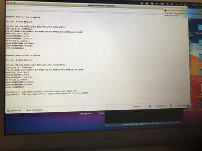
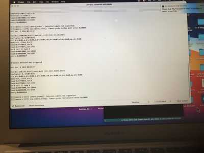
I just cleaned the camera connections and the message stayed the same, "camera module not supported"
Can you suggest another board brand other than the AI Thinker that I can get in a few days?
thanks,
Joel
@ drjoelleon
I have not seen that error message before, so am unsure what initiates it in your code. The cleaning of camera contacts arises from error messages concerning this error message 'camera probe failed with error 0x20001 Camera init failed with error 0x20001
This is sourced from here https://randomnerdtutorials.com/esp32-cam-troubleshooting-guide/
This guide has a whole realm of errors that can occur plus solutions, worth a look.
I am actually trying to obtain AI Thinker ESP boards myself, as they are considered the best and easiest to use. Unnamed boards are copies and may have errors associated, especially some pins assignments.
Back to your error message.
Can you copy and paste exactly what is displayed in full? Is there not a code on the monitor as well?
Can you paste your code covering the section of your camera model, at this point in the CameraWebServer sketch, then I can see what you have initiated there. This is my code from the same place, and I am using a non AI Thinker board, yet I select for that camera model.
#include <esp_camera.h>
#include <WiFi.h>

//
// WARNING!!! PSRAM IC required for UXGA resolution and high JPEG quality
// Ensure ESP32 Wrover Module or other board with PSRAM is selected
// Partial images will be transmitted if image exceeds buffer size
//

// Select camera model
//define CAMERA_MODEL_WROVER_KIT // Has PSRAM
//#define CAMERA_MODEL_ESP_EYE // Has PSRAM
//#define CAMERA_MODEL_M5STACK_PSRAM // Has PSRAM
//#define CAMERA_MODEL_M5STACK_V2_PSRAM // M5Camera version B Has PSRAM
//#define CAMERA_MODEL_M5STACK_WIDE // Has PSRAM
//#define CAMERA_MODEL_M5STACK_ESP32CAM // No PSRAM
#define CAMERA_MODEL_AI_THINKER // Has PSRAM
//#define CAMERA_MODEL_TTGO_T_JOURNAL // No PSRAM

#include "camera_pins.h"
Then the next information required is what you are selecting when you are uploading the code for you board, from the tools menu.
For example, I'm using Board "ESP Wrover Module" - ESP32 Arduino - ESP32 Wrover Module etc etc
Aye Kim
these are the Serial Windows I even have the brownout back.
I just got a new esp32-cam board and have the same problem. I tried the other esp32 board software from the tools menu but that didn’t work either. Any further suggestions?
Thanks,
Joel
PS maybe I should wait until I get the AI Thinker board?
Hi,
I'm sorry, photos of your screen show the error ok but why can you not put the actual code from your sketch up as requested please. Its the code you enter that results in the information created to display on the screen, all we are seeing is the screen stuff, we need to see the EGG that created the chicken.
In my previous post, the stuff in the blued box is what we want to see. If you scroll up this screen, on the right opposite your first post is a menu headed Forum Help Menu, the fifth line shows you how to add code to your post.
NOTE: all my boards (5) are non AI Thinker - and they ALL operated eventually.
Without your code there is no more help I can give, sorry.
Kimosubby
I'm also seeing another error on your screen that says "detected camera not supported"
Do you only have ONE camera selected from the list ?
Maybe if you were to post a copy of the code you're using like @kimosubby requested, somebody might be able to get a better idea what's happening
thanks for your help
i finally got the camera to work
i heard Bill mention that to eliminate the brownout he used a USB power hum and it is 5 v. This time i heard it and switched the jumper and power connector to 5v. That’s all it took.
thanks to you and the Forum for your encouragement I stuck with it and the solution appeared.
Hi both, good news for you Joel, you gotta keep messing.
As @Spyder confirms, posting your code is essential to fault finding. Similar error messages can result from very dissimilar coding errors/selections.
And just to stir the pot, my latest batch of three ESP32-cams, purchased on the understanding that they would be AI THINKER branded have arrived and are actually HW-297 boards. So it looks like authentic AI boards are hen's teeth!
Oh, they functioned first time though with 3.3V and no aerial attached. So now I have 8 to play with! I'll stick at that for a time.
Aye, Kim
this is the code I don't know how to fix the errors. If you can advise me it would be appreciated.
//
// WARNING!!! PSRAM IC required for UXGA resolution and high JPEG quality
// Ensure ESP32 Wrover Module or other board with PSRAM is selected
// Partial images will be transmitted if image exceeds buffer size
//
// Select camera model
//#define CAMERA_MODEL_WROVER_KIT // Has PSRAM
//#define CAMERA_MODEL_ESP_EYE // Has PSRAM
//#define CAMERA_MODEL_M5STACK_PSRAM // Has PSRAM
//#define CAMERA_MODEL_M5STACK_V2_PSRAM // M5Camera version B Has PSRAM
//#define CAMERA_MODEL_M5STACK_WIDE // Has PSRAM
//#define CAMERA_MODEL_M5STACK_ESP32CAM // No PSRAM
#define CAMERA_MODEL_AI_THINKER // Has PSRAM
//#define CAMERA_MODEL_TTGO_T_JOURNAL // No PSRAM
#define LED_Builtin 4
const char *ssid = "jml's Soft Access Point";
const char *password = "";
#include "esp_camera.h"
#include <WiFi.h>
#include <WiFiClient.h>
#include <WiFiAP.h>
#include "camera_pins.h"
WiFiServer server(80);
void startCameraServer();
void setup() {
Serial.begin(115200);
Serial.setDebugOutput(true);
Serial.println();
camera_config_t config;
config.ledc_channel = LEDC_CHANNEL_0;
config.ledc_timer = LEDC_TIMER_0;
config.pin_d0 = Y2_GPIO_NUM;
config.pin_d1 = Y3_GPIO_NUM;
config.pin_d2 = Y4_GPIO_NUM;
config.pin_d3 = Y5_GPIO_NUM;
config.pin_d4 = Y6_GPIO_NUM;
config.pin_d5 = Y7_GPIO_NUM;
config.pin_d6 = Y8_GPIO_NUM;
config.pin_d7 = Y9_GPIO_NUM;
config.pin_xclk = XCLK_GPIO_NUM;
config.pin_pclk = PCLK_GPIO_NUM;
config.pin_vsync = VSYNC_GPIO_NUM;
config.pin_href = HREF_GPIO_NUM;
config.pin_sscb_sda = SIOD_GPIO_NUM;
config.pin_sscb_scl = SIOC_GPIO_NUM;
config.pin_pwdn = PWDN_GPIO_NUM;
config.pin_reset = RESET_GPIO_NUM;
config.xclk_freq_hz = 20000000;
config.pixel_format = PIXFORMAT_JPEG;
// if PSRAM IC present, init with UXGA resolution and higher JPEG quality
// for larger pre-allocated frame buffer.
if(psramFound()){
config.frame_size = FRAMESIZE_UXGA;
config.jpeg_quality = 10;
config.fb_count = 2;
} else {
config.frame_size = FRAMESIZE_SVGA;
config.jpeg_quality = 12;
config.fb_count = 1;
}
#if defined(CAMERA_MODEL_ESP_EYE)
pinMode(13, INPUT_PULLUP);
pinMode(14, INPUT_PULLUP);
#endif
// camera init
esp_err_t err = esp_camera_init(&config);
if (err != ESP_OK) {
Serial.printf("Camera init failed with error 0x%x", err);
return;
}
sensor_t * s = esp_camera_sensor_get();
// initial sensors are flipped vertically and colors are a bit saturated
if (s->id.PID == OV3660_PID) {
s->set_vflip(s, 1); // flip it back
s->set_brightness(s, 1); // up the brightness just a bit
s->set_saturation(s, -2); // lower the saturation
}
// drop down frame size for higher initial frame rate
s->set_framesize(s, FRAMESIZE_QVGA);
#if defined(CAMERA_MODEL_M5STACK_WIDE) || defined(CAMERA_MODEL_M5STACK_ESP32CAM)
s->set_vflip(s, 1);
s->set_hmirror(s, 1);
#endif;
/*WiFi Starts here&&&&&&&&&&&&&&&&&&&&&&&&&&&&& */
void setup() {
pinMode(LED_BUILTIN, OUTPUT);
Serial.begin(115200);
Serial.println();
Serial.println("Configuring access point...");
// You can remove the password parameter if you want the AP to be open.
WiFi.softAP(ssid, password);
IPAddress myIP = WiFi.softAPIP();
Serial.print("AP IP address: ");
Serial.println(myIP);
server.begin();
Serial.println("Server started for jml's AP soft &&&&&&&&&&&&&");
}
void loop() {
WiFiClient client = server.available(); // listen for incoming clients
if (client) { // if you get a client,
Serial.println("New Client**************************."); // print a message out the serial port
String currentLine = ""; // make a String to hold incoming data from the client
while (client.connected()) { // loop while the client's connected
if (client.available()) { // if there's bytes to read from the client,
char c = client.read(); // read a byte, then
Serial.write(c); // print it out the serial monitor
if (c == '\n') { // if the byte is a newline character
// if the current line is blank, you got two newline characters in a row.
// that's the end of the client HTTP request, so send a response:
if (currentLine.length() == 0) {
// HTTP headers always start with a response code (e.g. HTTP/1.1 200 OK)
// and a content-type so the client knows what's coming, then a blank line:
client.println("HTTP/1.1 200 OK");
client.println("Content-type:text/html");
client.println();
// the content of the HTTP response follows the header:
client.print("Click <a href=\"/H\">here</a> to turn ON the LED.<br>");
client.print("Click <a href=\"/L\">here</a> to turn OFF the LED.<br>");
// The HTTP response ends with another blank line:
client.println();
// break out of the while loop:
break;
} else { // if you got a newline, then clear currentLine:
currentLine = "";
}
} else if (c != '\r') { // if you got anything else but a carriage return character,
currentLine += c; // add it to the end of the currentLine
}
// Check to see if the client request was "GET /H" or "GET /L":
if (currentLine.endsWith("GET /H")) {
digitalWrite(LED_BUILTIN, HIGH); // GET /H turns the LED on
}
if (currentLine.endsWith("GET /L")) {
digitalWrite(LED_BUILTIN, LOW); // GET /L turns the LED off
}
}
}
// close the connection:
client.stop();
Serial.println("Client Disconnected.");
}
}
Hi again.
I thought you stated in your post dated 2021-06-02 "i finally got the camera to work" and then went on to say how using 5V source solved the problems.
If you got your cam up and working then there's no errors in the code that you used. Spyder and myself thought you might be unchecking multiple camera selection choices, but you haven't. That's the only part of the code you 'tinker with' (pun). If there were errors then why did it work? I'm sorry but I cannot see what you are now trying to investigate.
If it works, and you say it does, then it ain't broke.
Aye, Kim
I bought a pair of ESP32-CAM from the same vendor. Packing says DFROBOT. Chip says ATHINKER, so I used ATHINKER successfully. Following the steps on "Getting started with the ESP32-CAM" I finally got 1 to work, one to kind of work.
Couple of troubleshooting tips:
1) The Hookup Diagram for FDTI shows the jumper in the 5V position, not the 3.3V position like it should be.
2) Putting the jumper in the 5V position and connecting to the 5V pin allowed me to load the sketch
3) If, after loading your sketch, removing the programming jumper, reattaching the USB cable, the initialization just ends with an endless line of “………” every few seconds, your SSID or password is wrong. SSID is case sensitive.
My problem:
I have 2 ATHINKER ESP32-CAMs. My first one will not stream, but will take a still shot. When streaming it shows a small blank square with a broken icon. The second one will stream just fine. Same sketch, wiring, computer, cable. Any ideas why?


