Evening all
(Well its evening here). I want to control a simple underwaterpump that uses only 5V with an ESP32. Now the esp32 has a 5V rail but it cannot drive the pump. I need to use an external powersource to drive it. No problem. But what is the best way to control the pump. I cannot seem to find 3.3V relay and when I connect a 5v relay (a FL-3FF) it seems to still draw too much current and the DHT22 and the capacitive soil sensor stop giving realistic outputs (the DHT22 just reports NaN).
I am thinking of using a TIP120 with IN4004 rectifier diode like in Bill's article. Would that work with the ESP32?
RonS
It should work fine with the TIP120 powering the pump from the 5V supply and the ESP controlling the TIP.
Anything seems possible when you don't know what you're talking about.
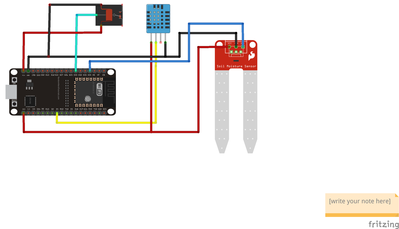
@ronsmitsnl, Hi, just a couple of questions...What are you using to power the ESp32, and could you furnish us with how you have the DHT22 wired up to the ESP32..
Since the relay you want to use is a 5 v dc, (FL-3FF) it has a minimum current draw of 100 mA, and this is why it's pulling down your 5 volt rail bus. The reason why I'm asking about what your using to power up you ESP32 is because you probably don't really need a relay.. just an BJT or Mosfet to drive the pump. What we need to know is what the pump specs are ( voltage and current ratings).
Regards,
LouisR
LouisR
Disclaimer:) I just downloaded fritzing, compiled it and made this sketch. the pump is this one: underwater pump. it should pull around 200mA. I tested this with the infamous dronebotworkshop bench powersupply (build from an old pc psu) and it pulls a bit over 250mA when running at 5V.
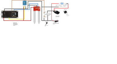
@ronsmitsnl, indeed, 250 mA is,about what I expected for the pump.. the relay should be about 100 mA or so, I would recommend your going to an external power supply like a Li-po battery pack using two 3.7 v rechargeable batteries, so that you will have 7.4 vdc as a source voltage. Then you can use a 5 volt regulator and a 2n2222 NPN BTL to control the relay.. This will also cut down on the regulators power dissipation rather than using a9 v battery ( 600 mW vs 1 W). The following fritzing will show you how to do this..
regards,
LouisR
LouisR
One observation I'd make is that the resistive water sensors are vulnerable to electrolytic erosion and chemical corrosion - you might want to consider a capacitive sensor. If not, don't run the sensor constantly - power it up, read the value, then power it down - and do that only as frequently as required - as part of your polling cycle.
I edit my posts to fix typos, correct grammar, or improve clarity. On-screen keyboards are evil.
@inst-tech Thank you very much for your help. It does raise some questions for me, as I am a newbie here. I was wondering why there is a voltage divider just before the 2n2222 diode. Using ohm's law this would mean that on the junction the diode only gets around 0.3 volts? the LM1117 threw me for a minute until I looked it up. I thought it was a mosfet but its a voltage regulator.
This setup will always be powered by a mobile phone charger. I will split the output of it in two, one to drive the esp32 and the other to drive the pump. So I think the LM1117 is not needed.
According to the sketch you made (again thank you :)) I would not even need a TIPS120 but only a 2n2222 diode to do the switching.
Again thanks 🙂
RonS
According to the sketch you made (again thank you :)) I would not even need a TIPS120 but only a 2n2222 diode to do the switching.
That 2N2222 is a transistor, not a diode.
Anything seems possible when you don't know what you're talking about.
According to the sketch you made (again thank you :)) I would not even need a TIPS120 but only a 2n2222 diode to do the switching.
That 2N2222 is a transistor, not a diode.
That shows you how much I still have to learn 🙂
That 2N2222 is a transistor, not a diode.
That shows you how much I still have to learn 🙂
That's what we're here for 🙂
Anything seems possible when you don't know what you're talking about.
mobile phone charger. I will split the output of it in two, one to drive the esp32 and the other to drive the pump.
Exactly what do you mean by 'split'?
According to the sketch you made (again thank you :)) I would not even need a TIPS120 but only a 2n2222 diode to do the switching.
And what do you mean by 'switching'
If you are going to power via mains to wall wart 'phone charger', I don't think you need any of the extra powering components that @inst-tech added.
First computer 1959. Retired from my own computer company 2004.
Hardware - Expert in 1401, and 360, fairly knowledge in PC plus numerous MPU's and MCU's
Major Languages - Machine language, 360 Macro Assembler, Intel Assembler, PL/I and PL1, Pascal, Basic, C plus numerous job control and scripting languages.
Sure you can learn to be a programmer, it will take the same amount of time for me to learn to be a Doctor.
@ronsmitsnl, your very welcome..In this case, the transistor 2n2222, is operated in the saturation mode and the 1k resistor limits the current to the base to about 2.6 mA, so this provide a Hfe gain of about ~100 to the collector, with will be about 246 - 250 mA. The 10K resistor is just a pull-down resistor so when the input signal from the D33 pin goes low (0 volts) it ensures that the transistor turns off by pulling the base to ground (negative side of the power supply).. the following is a link to Transistor biasing calculations you might enjoy looking into to see how all of this works..
https://www.allaboutcircuits.com/textbook/semiconductors/chpt-4/biasing-calculations/
as @will has said.. that's what we all are here for.. to learn from each other. have fun on your project
@zander, I agree with you about the regulator and the batteries.. as @ronsmitsnl didn't include how the was powering the ESP32 and the pump in his fritzing draw, I just made an assumption that he was going to use an external supply for power the pump.. At any rate, this will give him more options for future projects that may have need of this type of circuitry. The circuit as is can be used for remote locations where Mains power is not available, as all that would be needed is to supply power to the barrel jack from the battery pack to provide power to the ESP32. Something else for him to play around with...lol
Regards,
LouisR
LouisR
Exactly what do you mean by 'split'?
And what do you mean by 'switching'
If you are going to power via mains to wall wart 'phone charger', I don't think you need any of the extra powering components that @inst-tech added.
I am going to cut the micro usb connector off, and redirect the 5 volt both to the esp32 and to the submergible pump.
Switching in this case means switching the pump on and off


