Hello friends, Recently I am working on a project where I should be sending the data form an ESP32 (dev kit board) to ESP8266 (NodeMCU) using ESP-now protocol, I am first storing the data in an array and then sending that array to the NodeMCU. This what I am trying achieve. There is no problem in sending the data.
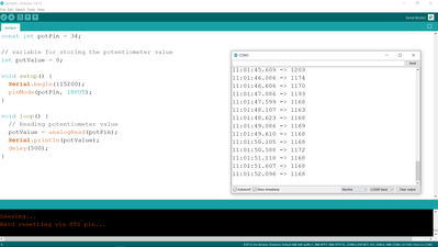
The problem is with reading the analog data. I am trying to read the data of an MQ-4 gas sensor. But the values are coming randomly around 950 to 1200 which is a huge margin of noise. When I ran the same code with the same sensor the values are around 235 to 250 in the Arduino UNO. I don't know what is causing the issue. I actually thought of sending the data of 6 to 7 sensors but there is even more noise with ESP-now. The values are jumping from 4095 to 0 almost randomly.
I am attaching the code that I am using for testing
const int potPin = 34;

// variable for storing the potentiometer value
int potValue = 0;

void setup() {
  Serial.begin(115200);
  delay(1000);
}

void loop() {
  // Reading potentiometer value
  potValue = analogRead(potPin);
  Serial.println(potValue);
  delay(500);
}
Intersting, the sample output you're showing seems to have settled to a fairly stable value around 1170. That corresponds to 1170/4096 = .286.
You say the UNO was producing results between 235 and 250; taking an average of 242/1024 gives a ratio of .236 which is lower than the EPS value but still comparable.
So, the sample data you supplied seems to indicate a stable condition at a slightly higher ratio than the UNO ?
Anything seems possible when you don't know what you're talking about.
So, the sample data you supplied seems to indicate a stable condition at a slightly higher ratio than the UNO ?
yes
Hi @svthb2_o,
Hopefully you have sorted your ADC problems, in which case, good luck with your project.
However, if not, a couple of suggestions, bearing in mind I am only guessing what circuit you are using:
- ESP32 is a 3.3V max processor, including ADC input. The MQ-4 data sheet I showed a 5V supply. That suggests risk of sending a voltage over 3.3V. (Obviously this depends upon your precise circuit details, including setting of variable resistor load.) I would consider using either a voltage divider or voltage clamp to protect the input.
- Temporarily replace the sensor with a potentiometer track (say 50kOhm) connected between 3.3V and ground, and measure wiper voltage ... I would hope the ADC value would only vary by about 1 (least significant bit), for any stationary wiper position.
- ESP32 WiFi appears to make large current peak demands, and 'chat' on the web suggests some/all of the commercial modules allow this to interfere with the processor operation, including sometimes causing brownouts.... this could suggest not only the 3.3V supply is dipping, but also the 'ground' voltage maybe rising above 0V. If it affects the 'digital' processor, then surely the ADC must also be affected?
- Try to check if the WiFI transmissions are affecting the readings e.g. does ADC behave when it isn't transmitting WiFi? If this is a problem, extra decoupling, etc. might help ... or maybe sequence the ADC reading into 'quiet' slots when WiFI is not transmitting ... this is simple in principle, but sorry I have no idea how easy that will be to achieve, since it might involve digging deep into the software library code.
Good luck .. I suspect others might be interested to know how you get on. Dave
@svthb2_o Your original values looked close to each other considering the Uno is a 10 bit ADC (0-1023 counts) and the ESP32 is a 12 bit ADC (0-4095 counts).
My last program I had problems with was, that I had had declared an AREF signal for the Uno and never connected the 3.3 volt power to the AREF input. Also, had to do some averaging of the input signal. I took 5 samples of the input and then created the average of them before using that number in a formula.
RCC1
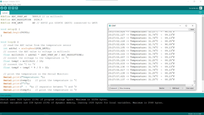
With little bit of tinkering I have few observations to share with you guys. So the code that I used for testing is below one.
#define ADC_VREF_mV 5000.0 // in millivolt
#define ADC_RESOLUTION 4096 // 1024 for ardino uno
#define PIN_LM35 35 // ESP32 pin GIOP36 (ADC0) connected to LM35 // A0 for // arduino

void setup() {
Serial.begin(9600);
}

void loop() {
// read the ADC value from the temperature sensor
int adcVal = analogRead(PIN_LM35);
// convert the ADC value to voltage in millivolt
float milliVolt = adcVal * (ADC_VREF_mV / ADC_RESOLUTION);
// convert the voltage to the temperature in °C
float tempC = milliVolt / 10;
// convert the °C to °F
float tempF = tempC * 9 / 5 + 32;

// print the temperature in the Serial Monitor:
Serial.print("Temperature: ");
Serial.print(tempC); // print the temperature in °C
Serial.print("°C");
Serial.print(" ~ "); // separator between °C and °F
Serial.print(tempF); // print the temperature in °F
Serial.println("°F");

delay(500);
}
This time I have used LM35 for testing so that I can have some reference. The temperature in my locality is 31 C according to google.
So first from Arduino at 5v given to the sensor
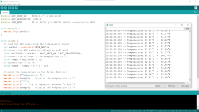
Now for ESP32 3.3v given to the sensor and sometimes its giving 35 to 40 C for some reason but its one reading only
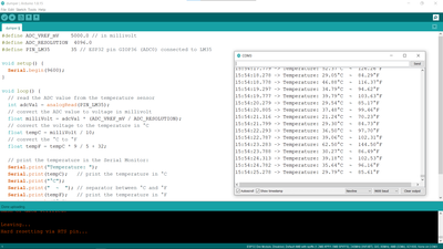
ESP32 5.0v given to the sensor (source from arduino uno 5v) its full of random values
Final observation is that both ESP32 outputs have not matched and had a difference of 3 to 4 C.
#define ADC_VREF_mV 5000.0
My last program I had problems with was, that I had had declared an AREF signal for the Uno and never connected the 3.3 volt power to the AREF input. Also, had to do some averaging of the input signal. I took 5 samples of the input and then created the average of them before using that number in a formula.
This line playing a major role for ESP32, I think its depending on the input voltage for the ESP32 board. If 3.3v given its not working. Now I will be sending this data to another ESP module using ESP now module again and update the weird effects that I gonna observe here.
Sai Venkat
@svthb2_o, Hi, just a couple observations here on your project.
First, the AREf that you are using should be a precision voltage reference like Adafruit LM4040.
2.048 V AREF for a 3.3 volt IO like the ESP32, and a 4.096 V AREF for the Arduino UNO.
The resolution of the ESP32 's 4096 count ADC would then be 2.048/4096= .0005 v, ( 0.5mV)
The resolution of the Arduino UNO's 4.096 count ADC would then be 4.096/1024= 0.004 v ( 4.0 mV)
Results are the ESP will have 8 times the sensitivity of the UNO.
This means that noise on the ESP32 can be picked up and will be counted as signal input.. this may be why you are seeing such a large variance in the ESP32 readings. If you look at the specs of the MQ-4 gas sensor, you will note that the Standard detecting temperature spec is 20°C +/- 2°
Using an external voltage reference will help, but at higher temperatures, that 2°c error will likely be larger.
These are not precision temperature elements and are just used to calculate ppm Gas concentrations for the Gas sensor, so it doesn't have to be that accurate as temperature changes will not be that drastic for what your are trying to do..
The following formula derived from the Ideal Gas Law relates changes in air volume to temperature, pressure and the number of molecules present:
ppm corrected = ppm measured * ((Tmeasured*pref) / (pmeasured*Tref))
- pmeasured = Current pressure, in the same units as reference pressure (not corrected to sea level)
- Tref = reference temperature, usually 25°C, 77°F, converted to absolute (298.15 for °C, 536.67 for °F)
- Tmeasured = Current absolute temperature, °C + 273.15, °F +459.67
pref = reference Barometric Pressure, usually sea level, 29.92 in Hg, 760 mm Hg, 1013.207 hPa or 14.6959 psi.
Hope this information helps you understand what's going on..
Regards,
LouisR
LouisR
2.048 V AREF for a 3.3 volt IO like the ESP32, and a 4.096 V AREF for the Arduino UNO.
First of all Thank you 😀 LouisR for your explanation it helps me in understanding what is happening. How to choose AREF for any sensor is it form data sheet of microcontroller ?
@svthb2_o, The choice for what AREF depends on what Vcc your board requires..in your case the Vcc of your ESP32 uses 3.3 volts, so that you would limited to 2.048 v or 1.014 V reference voltage.
The problem with the voltage references is that you can not exceed the input voltage to your ADC that is greater than what your reference voltage is. In other words, your input voltage to your analog input can not exceed the 2.048 V reference voltage on your ESP32, or the 4.096 V reference voltage on your Arduino UNO.. Also, do not try to power up anything with those reference voltage modules.. they have no current capabilities, their sole purpose is to supply the ADC with a highly stable voltage reference.
See this link to refresh your memory on how to wire them up to your boards, and what they do.. https://dronebotworkshop.com/dc-volt-current/
Good luck, have fun, and be safe!
kind regards,
LouisR
LouisR
So this weekend passed spending most of my time in the boiler room with my laptop debugging ESP32 ADC values.
I've been using an arduino mini (for ADC) connected via USB/SPI to a RPi 3 for some four years now to register oil heater run times for oil consumption measuring. I simply measure the volume of the burner with a cheap microphone card which outputs analog values relative to volume. That concept has worked flawlessly and reliably all the time but now I wanted to free the RPi and Mini for other uses.
But what I found was that the ESP32 ADC readings are all over the place so that I finally came to the conclusion that it is not going to work. I tried all possible tricks that came to mind to smoothen the readings starting from external capacitor to byte value averaging but to no avail. As the code is basically the same as for the arduino the conclusion is that it the culprit must be the ESP32 ADC and nothing else.
After all that jargon my simple question is if someone has information of if the ADC problems have been fixed in the newer models? I've been using a WROOM32, probably manufactured sometimes in 2019.
Thanks and cheers,
Carro
PS. For a solution to my current problem I've ordered a couple of ADS1115 I2C AD converters.
@carro007 You should start your own topic rather than jumping on another person's topic, that way we don't get confused.
First computer 1959. Retired from my own computer company 2004.
Hardware - Expert in 1401, and 360, fairly knowledge in PC plus numerous MPU's and MCU's
Major Languages - Machine language, 360 Macro Assembler, Intel Assembler, PL/I and PL1, Pascal, Basic, C plus numerous job control and scripting languages.
Sure you can learn to be a programmer, it will take the same amount of time for me to learn to be a Doctor.
Sorry if you got confused. Same problem with the OP so no reason to start a new thread.
Carro


