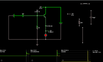
I was playing around with circuitjs, experimenting with an NPN transistor. The circuit is very basic, but the curious thing is, the peak current measured by the ammeter (connected to the emitter) is 23A! Peak voltage at the base was just under 5V. I know it's only a simulator but it's fun to play around with. Also, I can't destroy an oscilloscope in a simulation. Or if I do, my wife won't get mad! 😀
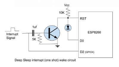
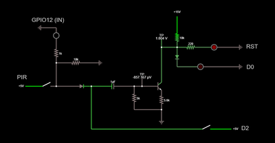
I'm trying to learn about transistors and capacitors to create a circuit that will wake an ESP8266 from a deep sleep using a PIR sensor as a trigger. Here's an example I found online, which I am trying to piece together and understand.
I assume this is where you got the circuit from?
https://diyprojects.io/esp8266-deep-sleep-mode-test-wake-pir-motion-detector/#.YEBIoo4zbIU
It is.
I'm not exactly experienced with looking at circuits, but I think I understand what is happening in that second circuit.
For starters, the 8266 RST pin activates and resets the chip when it is pulled low. In your "stable" state with the appropriate firmware for this circuit, RST is held high by the Vcc source connected via the pullup resistor (which draws no appreciable current).
Ignoring the transistor for a moment, D0 is your "Wake" pin, and is be controlled by an internal 8266 timer. When the timer expires, D0 will switch low (internally connected to ground), which will overpower the 10k pull-up resistor, and drag RST to ground, triggering a wakeup.
The left side of the circuit (everything left of and including the transistor) is part of the "react to a trigger event" alternative to the timer-based wake. The capacitor/resistor combo (the term to google for is an "RC Differentiator") turns the incoming interrupt square wave into a short "pulse", that grounds the RST pin by an alternative route.
When activated, the 8266 firmware will check D2/GPIO4 to see if it was woken up by a triggering event... which should still be available if (and only if) the interrupt signal lasts long enough.
On the first circuit, the circuitjs one... I'm somewhat hampered by the fact that I'm not sure what the red circle is. If that's an LED... I humbly submit that in a non-simulator it would be an ex-LED. Your initial pulse from the RC differentiator likely saturates the transistor. Without a current limiting resistor in series with the LED, the current goes a little bit nuts in that non-current-limited right-hand-side loop.
"A resistor makes a lightbulb and a capacitor makes an explosion when connected wrong"
"There are two types of electrical engineers, those intentionally making antennas and those accidentally doing so."
The first circuit doesn't make any sense to me. The capacitor would be acting like a open circuit thus no base current and thus no collector current.
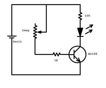
When the transistor is operated as a switch you do need a resistor to limit the current through the LED when the transistor is ON.
https://www.electronicshub.org/transistor-as-a-switch/
Have you tried real circuits in the simulator to test your understanding.
Here is a very simple example which demonstrates transistor operation.
I have tried a simple circuit to test a transistor. I was breaking down the other circuit I posted to try to understand what it was doing.
I think the circuit maintains zero (or rather a very low) current to the base to keep the transistor off. When motion is detected, the interrupt signal goes high and the capacitor causes a high pulse (I'm speculating here), which quickly turns the transistor on and off again. I think the falling edge of this is supposed to trigger the RST pin, which wakes up the 8266.
Oh and yes, I had a resistor to protect the LED, but I took it out when I was switching things in and out of the circuit and moving components around, and I forgot to put it back in. No smoke in the sim!
Thanks!
The first circuit doesn't make any sense to me. The capacitor would be acting like a open circuit thus no base current and thus no collector current.
This is the eventual stable state, but when you first start the sim (or circuit... if you imagine there's a switch being closed between the capacitor and the battery) the capacitor does let the rising edge through as a pulse, which then fades down through the resistor.
A few microseconds into the simulation, this current passes through the base->emitter of the transistor, and the collector->emitter will allow 100x that current through (or whatever the "beta" or "Hfe" multiple of the transistor is).
"A resistor makes a lightbulb and a capacitor makes an explosion when connected wrong"
"There are two types of electrical engineers, those intentionally making antennas and those accidentally doing so."
if you imagine there's a switch being closed between the capacitor and the battery
Sure I did imagine that but the simulator surely needs that switch to be there to operate that way?
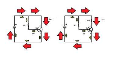
Once you get that the base current controls the collector current then visualizing the transistor operation becomes easy. The collector current is some multiple of the base current say 1000 times.
So in the example below select Rb to limit the base current Ib to some very low value.
The resulting collector current Ic will be some multiple of that current.
Now place a resistor Rc in the collector path and you will see the collector current Ic will remain constant within limits. The resistance between the collector and emitter will adjust to try and maintain a collector current Ic value some multiple of the base current Ib. In your simulator you can make the resistor Rc variable to see what happens as you change its value.
To enlarge image right click with mouse and choose open link in new window.
I managed to get the circuit working with my ESP8266. It wakes itself up every minute or it wakes up if there is motion detected by the PIR. D2 (in the schematic) and the interrupt signal generate a pulse to RST thanks to the capacitor and transistor.
However, there's one aspect that doesn't work for me and that is the ESP8266 also needs to know when the PIR no longer detects motion (the signal interrupt changes to LOW).
So I'll either have to rethink the circuit or abandon using components and do it all in software (ESP8266 interrupt for motion and a manual timer for the periodic check of the temperature.
if you imagine there's a switch being closed between the capacitor and the battery
Sure I did imagine that but the simulator surely needs that switch to be there to operate that way?
Usually not. The simulator is going to start at t=0 as if all the components magically assembled themselves instantly, in a remarkable entropy violation. 🙂
Although... if the last wire you connect is the transistor base it's not far off.
"A resistor makes a lightbulb and a capacitor makes an explosion when connected wrong"
"There are two types of electrical engineers, those intentionally making antennas and those accidentally doing so."
I like components that magically assemble themselves! It makes me feel far more intelligent than I actually am!
I wonder if the following addition would work. I admit the schematic is confusing as I'm working with circuitjs and the easiest way for me to simulate things is to use a switch for the PIR sensor, and an LED + resistor for the two input pins into the ESP8266.
When the PIR detects motion, it outputs HIGH. The transistor's base is pulsed, which wakes up the ESP8266 (via the RST pin). The ESP8266 reads GPIO12, which is HIGH and knows it was woken by the PIR
The ESP8266 then installs an ISR to listen for the falling edge on GPIO12, at which point it can go back into a deep sleep.
GPIO12 will be LOW if the ESP8266 is woken by the deep sleep timer. It therefore knows it doesn't need to install an ISR for the PIR.
Does that make any sense?
It worked in circuitjs (I know that doesn't mean much) but the ESP8266 doesn't wake up when I wave my hand in front of the PIR. I might have to rebuild the breadboard from scratch, as I'm not sure what the problem is. Assuming the schematic is valid!
I re-organised my code (I'll try to post it later once I've tidied it up), re-checked the wiring and it seems to work. The ESP8266 is now woken from a deep sleep by its timer or by the PIR sensor. Nice!

