Hi @yurkshirelad,
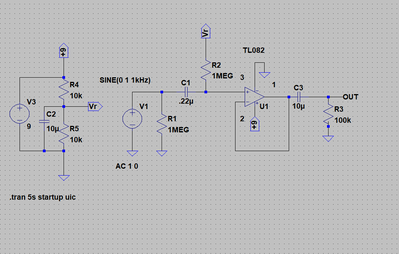
I am not clear if the DC voltage of 2.3V you report refers to your simulation or a 'real' circuit.
Looking at the TI data sheet, the op amp is clearly aimed at split voltage of at least +/-5V, so there might be an issue with your 9V supply.
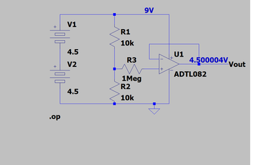
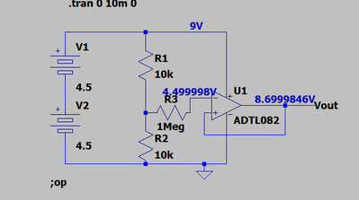
I don't know which TL082 model you are using .. so I tried the AnalogDevices near equivalent which has a model in LTSpice .. with a simplified 'DC only' circuit.
This is for DC operating position ... and Transient gives the same result .. with the non-inverting input at 4.5V as you expected.
Hope this helps. Best wishes.
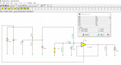
I get pretty much the same thing. See the voltmeter readings (VM) in the chart. I used the TINA software from Texas Instruments.
RCC1
It's a real circuit.
Hi @yurkshirelad,
Ok, so it is the real circuit that isn't playing nicely .. sorry I can't see why not from the information provided although I haven't tried to build it myself.
Perhaps you have a faulty chip?
I suggest you strip your real circuit back to the minimum, similar to my simulation, and try to find your way from there. Note, I would add decoupling capacitors to the supply, just in case it has found a way of oscillating .. you don't need these for a simulation to work, but real life can be different!
Good luck! Dave
Thanks guys.
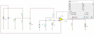
If your capacitor C1 is somehow shorted, you end up with a second voltage divider (Divides your 4.5 VR in half). I added a jumper across the C1 in the simulation circuit and removed the sin wave generator. The simulation then gives me a 2.24 volt reading at the op amp non-inverting input (VM3). Sounds close to what the real circuit was giving you.
I also had to correct my drawing because I had the inverting and non-inverting inputs to the op amp different than your schematic.
RCC1
Hmmmm, good observation. I'll have to carefully check but I don't see how it could be shorted to ground. R2 should prevent it grounding back via the power circuitry. R1 should also be OK. The only option I see if somehow it's grounding via the input guitar signal? Will investigate.... Thanks!
Hi @yurkshirelad and @rcc1,
Well done @rcc1 for finding a plausible cause. When you get something strange like this, cutting back to the minimum circuit, and then gradually building it back up will usually reveal an unexpected cause. I know from bitter experience, how easy it is to make a wiring mistake or similar.
I would also measure and write down the voltage on each of the opamp pins ... look for any clues.
===============
A little off the problem of the specific unit, but I also noted some strange simulation behaviour...
I didn't notice that the first diagram from @rcc1 accidentally had the feedback to the non-inverting terminal when it was first posted, but I am confused as to how the output voltages were still 4.5V mid-point, whilst I would have expected a 'dramatic' result.
I tried to repeat the simulation with LTSpice and it showed a more plausble result:
ie any small positive voltage on the output has been fed back into the non-inverting input, to drive the output much more positive, until it reaches as close as it can to the positive rail.
.....
I then tried to repeat with Tina ... which I downloaded for the purpose, using Tl081 as the nearest in its default library... and found a similar result (VF1 output voltage 4.49V) to @rcc1 above ... which I do not understand!
Nodes Values
I_R1[0,VF2] -4.5mA
I_R2[VF2,1] -4.5mA
I_R3[VF2,4] 24.97pA
V_R1[0,VF2] -4.5V
V_R2[VF2,1] -4.5V
V_R3[VF2,4] 24.97uV
V_V1[1,0] 9V
VF1 4.49V
VF2 4.5V
Does Tina know something I don't ... or is it misleading us? I think I may stay with LTSpice for a while.
Best wishes, Dave
Turns out the polarity of C1 was wrong and it formed another voltage divider with R1 and R2. Doh! The anode was supposed to connect to the op amp. The diagram shows a ceramic capacitor but I was using an electrolytic.
Hi @yurkshirelad,
Great to see you have tracked the problem down.
As a comment, had you drawn your circuit with an electrolytic, on a good day, I would have questioned its suitability given it is surrounded by high value resistors.
Electrolytics provide high capacitance at the expense of high leakage currents, as well as being polarity conscious ..
Since, 1 microAmp through 1 MegOhm resistance means 1 volt drop ..
Electrolytics in coupling circuits like this should be limited to cases where source resistors are less than a few kOhms, and even that is pushing your luck.
Hope the guitar is now sounding good! Dave

