We might need to consider the resistive load.
https://www.khanacademy.org/science/electrical-engineering/ee-circuit-analysis-topic/ee-resistor-circuits/a/ee-voltage-divider
The assumption also is you have a constant voltage source.
I remember learning how to build my own ADC before IC chips became available to do the job or one was inbuilt into a microprocessor. I like to know how circuits work at the level of the discrete components used.
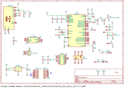
@inq Yep.. you got!.. I finally found what I was looking for..here the link.. https://siytek.com/wemos-d1-mini-analog-input/#ESP8266-Analog-To-Digital-Converter-Specification scroll down to the heading
"What is the maximum Wemos D1 Mini analog to digital converter voltage?"
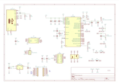
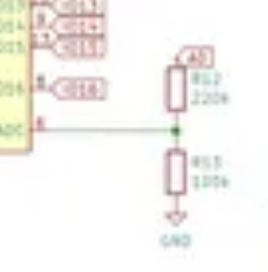
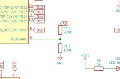
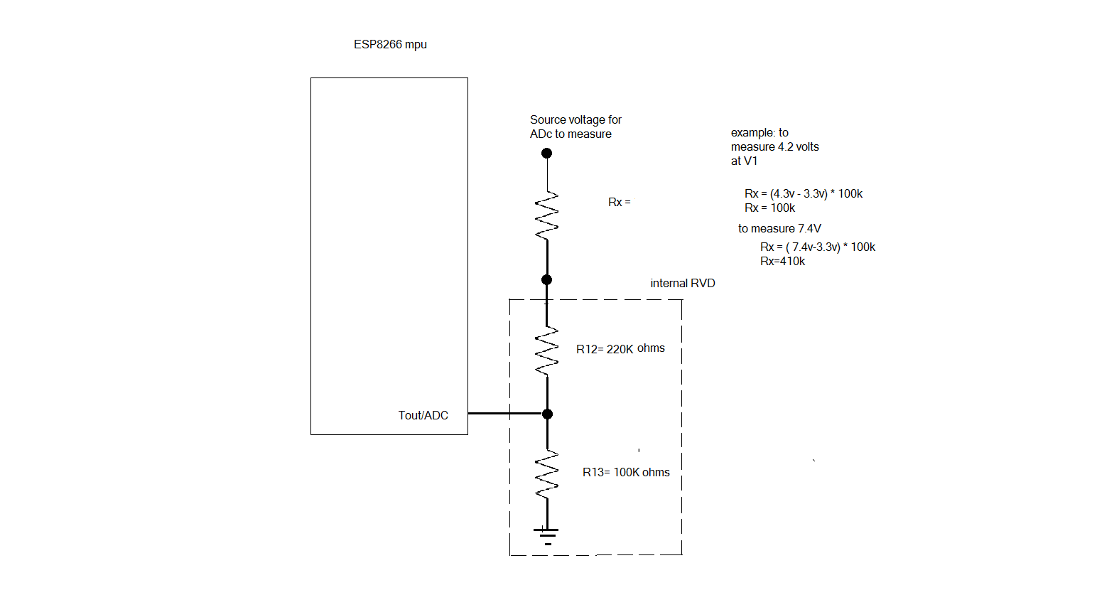
and you'll see the schematic.. blow it up and look at section c5 , and note the RVD that R12, and R13 make to the Tout/ADC and that R12 goes to the pin A0..so, yes we are just extending the RVD network by adding in another resistor. So for each voltage > 3.3v, we just add another 100k to it..
example; if we wanted to measure a 7.4V , we would just do this ( 7.4-3.3) * 100K= 410k resistor..
I would use precision resistor of 1% or less to keep the resolution in check.. but ya, that's all there was to it. took me long enough to find it...lol
LouisR
@robotbuilder See my recent reply to @inq, it details how it works..and thanks for comment..I too always want to know how circuits work, as it's very difficult to trouble-shoot a problem when you don't know how it's suppose to work.. learned that lesson over the 40 years of trouble shooting industrial process controls.
you da man!
regards,
LouisR
LouisR
and you'll see the schematic.. blow it up and look at section c5 , and note the RVD that R12, and R13 make to the Tout/ADC and that R12 goes to the pin A0..so, yes we are just extending the RVD network by adding in another resistor. So for each voltage > 3.3v, we just add another 100k to it..
You're so funny! 🤣
No wonder I never found those resistor values. If I ran into that picture, my eyes would roll up in my head, I'd fall out of the chair and start foaming at the mouth. Then I'd quickly scroll down to hide it.
I think that is what it says.... 220K and 100K. 🤗
3 lines of code = InqPortal = Complete IoT, App, Web Server w/ GUI Admin Client, WiFi Manager, Drag & Drop File Manager, OTA, Performance Metrics, Web Socket Comms, Easy App API, All running on ESP8266...
Even usable on ESP-01S - Quickest Start Guide
The assumption also is you have a constant voltage source.
I'm not sure I understand, but I'll swing anyway...
Are you talking about a constant voltage powering the WeMos so it has a reference voltage to compare???
If yes...
I believe the battery shield does that.
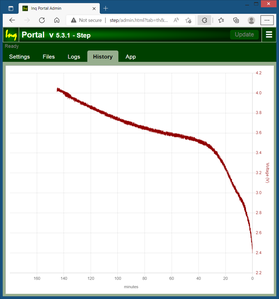
Even though the wire from the positive terminal (see picture somewhere above) through the 100K ohm to the A0 pin resulted in the curve above, I routinely checked the voltage powering the Vin pin of the WeMos... it varied from 4.98 to 5.01 even just before the shield crapped out at 2.5V as detected by the A0 pin.
If no...
Please explain. I'd like to understand the EE concepts.
VBR,
Inq
3 lines of code = InqPortal = Complete IoT, App, Web Server w/ GUI Admin Client, WiFi Manager, Drag & Drop File Manager, OTA, Performance Metrics, Web Socket Comms, Easy App API, All running on ESP8266...
Even usable on ESP-01S - Quickest Start Guide
@inq Where is the pin in that diagram, and is that circuit the same as @inq showed us earlier, I don't think so but I am old and tired. I am thinking I can learn something from all this so I am curious.
First computer 1959. Retired from my own computer company 2004.
Hardware - Expert in 1401, and 360, fairly knowledge in PC plus numerous MPU's and MCU's
Major Languages - Machine language, 360 Macro Assembler, Intel Assembler, PL/I and PL1, Pascal, Basic, C plus numerous job control and scripting languages.
Sure you can learn to be a programmer, it will take the same amount of time for me to learn to be a Doctor.
@robotbuilder - I can read that even without my glasses. 🧐
3 lines of code = InqPortal = Complete IoT, App, Web Server w/ GUI Admin Client, WiFi Manager, Drag & Drop File Manager, OTA, Performance Metrics, Web Socket Comms, Easy App API, All running on ESP8266...
Even usable on ESP-01S - Quickest Start Guide
@robotbuilder Since the original image is a PNG file, there's not much you can do other than redrawing it and save it as a BMP, or JPG file.. The concept is as @inq has described in his post as a simple RVD ( resistive voltage divider) and boils down to that..mystery solved.
LouisR
The assumption also is you have a constant voltage source.
I'm not sure I understand, but I'll swing anyway...
Are you talking about a constant voltage powering the WeMos so it has a reference voltage to compare???
It was just a toss in comment. The voltage symbol is for an ideal voltage source which in theory will deliver as much current as you want (current increases as resistance decreases). But real batteries have an internal resistance in series with the ideal voltage source. You can also have an ideal current source which delivers a fixed current regardless of the resistance.
When I realised the image was from the link you gave I understood.
The article did give a link to a higher resolution version.
https://www.wemos.cc/en/latest/_static/files/sch_d1_mini_v4.0.0.pdf
To enlarge image right click image and open link in new window.
@robotbuilder Good catch @robotbuilder.. I so so excited about finding this schematic that I didn't look to see if there was a better resolution for it..lol
Anyway.. the mystery is solved, and we all learned something form it..I was pretty sure it had to be something like a RVD, but just needed to confirm it so as not to cause more confusion and misunderstanding.. Electronics can be hairy sometimes, but the basics always prevail...Thanks for the help!
Regards,
LouisR
LouisR

