Hi, I wish to control two stepper motors with one TB66000 controller
Both the stepper should work together doing exactly the same ..... they will be driving the gantry for a CNC machine one working from each side.
Many people must have been faced with this problem.... but, so far, I have not seen the solution.
Squeaky
Hi
Apologies if this is not what you are seeking but is this link any use to you:
https://wiki.dfrobot.com/TB6600_Stepper_Motor_Driver_SKU__DRI0043
Ron Bentley
Creativity is an input to innovation and change is the output from innovation. Braden Kelley
A computer is a machine for constructing mappings from input to output. Michael Kirby
Through great input you get great output. RZA
Gauss is great but Euler rocks!!
Question first: What is your concern with driving the two steppers? Is it in keeping the two synchronized? Is the issue with having enough power to drive then simultaneously?
From my understanding (no direct experiance) the motors can be connected in parallel provided they are the same type and that there is sufficent current capacity.
One concern I would have in doing this, is that the motor shafts can become out of sync, when power is removed. This could result with binding of the gantry. This is why you'll see dual screw implementations where one screw is driven by the other, by way of gears and a belt. I'm sure there are ways of keeping dual screws synced when driven by dual steppers, but don't know of any off-hand.
--
Dale
@squeaky, Hi, just a few notes on how you can connect the stepper motors to control them.
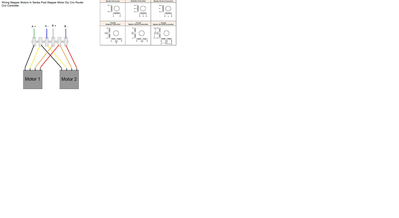
First, if connected in parallel, you will get the same voltage to each motor, but the current will be divided between them, so you may not have enough torque, only ~ half the current. In series, you will divide the voltage between the motors, but will have the maximum current necessary to produce the torque you need, if the motors are the same types.
Other concerns are that the power supply needs to be capable of delivering the current and voltage required. I've included an attached file to show you how to connect the motors in series.. hopes this helps you.. be sure to lets us know how your project progresses..
kind regards,
LouisR
LouisR
Thanks Ron and Newberry.
I had seriously considered the way you suggested but the thought of the two shafts becoming out of sync was a little worrying.
I am also a little concerned about waste material from machining getting caught up in the timing belt unless I can somehow adequately box them in
Squeaky
I think I'd prefer two steppers each with their own driver, with the simultaneity supplied by the wiring from the microcomputer. That is, both drivers are fed from the same micro controller pins.
Anything seems possible when you don't know what you're talking about.
Could you kindly resend the wiring diagram .... to small to get meaningful print
Squeaky
@squeaky A couple tips. When replying to a specific post, use either the reply icon at the bottom of the post, or use @username as in @squeaky that way he will be notified if he is subscribed to the convo.
As far as printing larger, what I did was click on the image in his post, then use a screen grabber to just select the image. That then fills a standard piece of printer paper.
First computer 1959. Retired from my own computer company 2004.
Hardware - Expert in 1401, and 360, fairly knowledge in PC plus numerous MPU's and MCU's
Major Languages - Machine language, 360 Macro Assembler, Intel Assembler, PL/I and PL1, Pascal, Basic, C plus numerous job control and scripting languages.
Sure you can learn to be a programmer, it will take the same amount of time for me to learn to be a Doctor.
Hi @squeaky,
Re:
I had seriously considered the way you suggested but the thought of the two shafts becoming out of sync was a little worrying.
Stepper motors are usually used in an 'open-loop' configuration, which means assuming that they will always achieve the motion commanded by the controller. Of course, a mechanical 'fault' such as a piece of swarf caught in the gearing could easily cause the affected motor to 'miss' some steps.
In terms of the basic 'electrics', I think trying to run two motors from one controller may increase the risk of them being 'underpowered' and hence liable to going out of sync due to any 'mechanical stiffness'. Hence the approach @will looks like a 'safer' approach. However, none of these approaches will guarantee that the motors will always stay in sync.
If staying in sync is a principal requirement, then you may like to consider monitoring the motion of each motor, and using the information to 'raise the alarm', presumably preventing further motion, if the motion signals do not match.
I have never built such a system, but if I were to try, I would probably start by looking at 'rotary encoders'.
A starting point might be deciding the maximum rotational error that could be tolerated by the system without causing a substantial problem --- this information would indicate the resolution the encoder would need to achieve.
I would expect the cost to increase with the resolution, so if (say) difference of up to 90 degrees could be tolerated, then a cheaper and simpler solution may be possible than say 1 degree.
NB a rotary encoder approach is more likely to work if the rotary motion is in the same direction for many rotations - each direction change may cause any backlash or assymetry between the two motor/encoders to introduce an extra pulse in one channel compared to the other. After several direction changes this may exceed the 'tolerance' of the detection system.
Good luck with your project Dave
Thanks Dave..... good food for thought
I have quite a lot to do before I need to take this decision .... At the moment I am toying with the idea of building a quite simple test rig to try out two motors driving something or other.
I actually have a small industrial CNC in my workshop and the gantry is powered by 2 NEMA 23 stepper motors but I am not brave enough to start fiddling about with this machine.
Squeaky
Hi @squeaky,
I think building a test rig is an excellent idea. Also take a good look at your CNC rig .. nothing destructive, but try to figure out as much you can. Some forethought is always a good idea, but the 'real world' always keeps some surprises that only become apparent when you do it for real.
As for the 'can I drive two motors with 1 controller?' ... I suspect the answer is maybe, but you are more likely to run into issues.
As I don't know this market, I did a quick Google and the first reply suggested a 6600 controller was £17 (~US $20) and a Nema23 motor £73 (~ US $80). I don't know if these are representative, but if you can get a controller for about $20 and a motor is about 5 times the price of a controller, then I think I would get a second controller!
-----------------
As @will suggested, in principal the signals from the Arduino could drive both controllers. However, there is a possible 'beware of gotcha' with that approach.
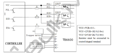
There appear to be many 'TB6600' controller boxes, presumably taking their 'name' from the Toshiba chip of the same number. Some of the respective controller box data sheets do not specify the electrical specifications of their input pins (drive, step and enable), but some more helpfully show optoisolators ... e.g. https://bulkman3d.com/wp-content/uploads/2019/06/TB6600-Stepper-Motor-Driver-BM3D-v1.1.pdf
From this, I would guess each input pin would draw about 10mA, when driven by a 5V logic chip. So putting two such inputs in parallel (for two controllers), the current estimate is 20mA.
At a quick check, this appears to correspond to the recommended maximum for the output from an ATmega328P ... the device used on the Arduino Uno.
So at first glance, (Please check carefully yourself ... I may have overlooked something.), it looks like @Will's suggestion will work, if you choose the Uno. Other Arduino type boards are also possible, but you must check the processor outputs are 5V, (some Arduino boards and the ESP8266/32s are 3.3V), and that the I/O outputs can handle at least 20mA each.
---------
Sorry if this sounds a little complicated ... in reality it is just a matter of looking for the right stuff! If you have a specific board in mind, then you could always try asking about it on the forum. I only looked up the Uno as I know it is a popular choice .. others may have useful advantages.
Good luck. Dave


