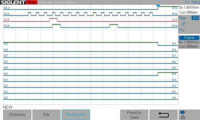
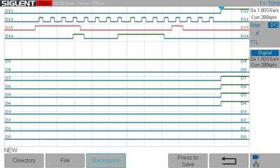
I have two 74HC595 shift registers that are cascaded. The code is working as it should unless I have a Serial.println anywhere in the code - even just the setup routine. What happens is that the data bits being shifted become rather random where I should only be shifting in one bit that is "on" but instead, I get multiple "on" bits being shifted in. See logic analyzer screenshots below. (I am using Arduino pins 4-6 to control the shift register.) I am also using PlatformIO and I have not tried downloading the code from the Arduino IDE to see if there is a difference in the Arduino default libraries. I have also used "nointerrupts()" prior to writing to the shift registers to no avail. Has anyone else seen this?
The redline (D15) on the scope traces is the serial data in that is connected to pin 14 of the first shift register. D11 are the shift clock pulses and D12 is the store.
Double-check all of your ground connections and make sure you have a capacitor across VCC and GND on your shift registers.
Anything seems possible when you don't know what you're talking about.
I have one capacitor on the VCC and ground where the Arduino connects to the breakout board.
I slowly whittling away at this and it looks like the output data that is being sent to the shift registers is getting corrupted prior to being shifted out - so the hardware is doing what it is being told. What is baffling is that the only thing that is different in the code is the enabling of the serial output. With the serial output, I only have 11 bytes left in the data memory due a couple of large arrays. When the code for the serial output is removed, I have 212 bytes of data memory remaining.
So yeah, I am pretty confused with what is going on.
(I am going to shift to a Mega since I am so close on memory.)
I shifted to a Mega and the problem went away. 😀
I am not sure what the root cause of the problem was, but everything is now working as it should, even with the serial port enabled. I needed to go to the Mega anyway, so I will have the data memory for additional functionality, but this was rather confusing.
Thanks
It would have been interesting if enough detail was given that someone could have wired up an identical version to see if they had the same issues.
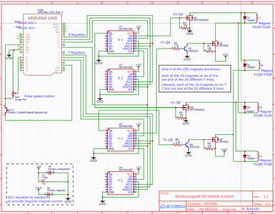
- @robotbuilder I am going to be out of town until next week but I will try to post a wiring diagram when I get back. I am using two sets of two cascaded 595s (total of 4) to control a target of 256 external devices (MOSFET controlled electromagnets). One set of registers controls the positive and the second set controls the negative so it is a multiplexed (is that the correct word?) 16 x 16 matrix. The project has taken on a life of its own!
Hi,
Sorry I’m a bit late to the party, just seen your post re conflicts with Serial.print and shift registers. Very pleased that you have resolved your issue, clearly the size of your sketch had reached the limits of your UNO!
It sounds like you have crafted a solution that is working as you wish for your needs using 74HC595 shift registers. I just wanted to signpost you to some work I did last year in developing a library that provides a different approach to designing solutions using these shift registers – the “ez_SIPO8_lib” library. Its called SIPO8 because the registers are Serial-In/Parallel-Out and based on an 8 bit architecture and, once you understand its concepts is easy (ez) to use (if I decide to develop a library based on the Paralle-In/Serial-Out then I suspect it will be called “ez_PISO8_lib”). The library is available on github and downloadable via the Arduino IDE Library Manager (Tools/Manage Libraries), search for “ez_SIPO8_lib” (v1.08).
It comes with a full User Guide, Crib Sheet and many examples. I won’t describe how this library differs from others available but you will understand how if you read the User Guide. Hope you find it of interest for your current and/or future considerations.
Github LINK.
Cheers
Ron B
Ron Bentley
Creativity is an input to innovation and change is the output from innovation. Braden Kelley
A computer is a machine for constructing mappings from input to output. Michael Kirby
Through great input you get great output. RZA
Gauss is great but Euler rocks!!
@robotbuilder Here is a snapshot of the circuit prior to going to an Arduino Mega. The sketch has a rather large array in it that pushed things almost to the limit and when I added the Serial.print statements, it appears values in the array were changed. Exact same sketch using a Mega is working fine.
Here is the part of the sketch that writes to the shift registers:
digitalWrite(latchPin_x, LOW); // Don't latch the output until all registers have been updated
digitalWrite(latchPin_y, LOW); // Don't latch the output until all registers have been updated
shiftOut(dataPin_x, clockPin_x, MSBFIRST, outputShiftRegister_x2);
shiftOut(dataPin_x, clockPin_x, MSBFIRST, outputShiftRegister_x1);
shiftOut(dataPin_y, clockPin_y, MSBFIRST, outputShiftRegister_y2);
shiftOut(dataPin_y, clockPin_y, MSBFIRST, outputShiftRegister_y1);
digitalWrite(latchPin_x, HIGH); // Output the data to the X shift registers
digitalWrite(latchPin_y, HIGH); // Output the data to the Y shift registers
Ok a bit more than I thought to try and wire up an identical version to see if they had the same issues glad you have it sorted 🙂


