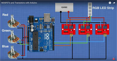
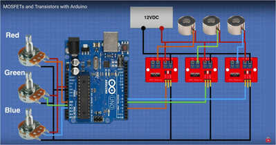
In Bill’s YT-video ‘MOSFETs and Transistors with Arduino’ I found the following instruction on how connect potmeters and mosfets to drive a RGB LED strip.
As a complete newby I want to control a handful of electromagnets (12V, P20/15, 25N).
Before I go ahead: are the following connections (at the top right) the way to go ?
Somebody here suggested I should connect the Battery (-) to the Arduino GND. Does that make sense?
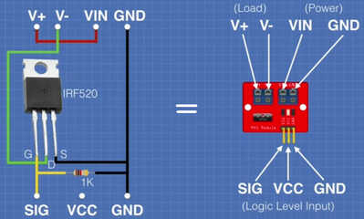
The question is what is the circuit of the driver modules? I'm assuming the common of the control input is connected to the common of the output circuit. In other words, the 2 black wires are internally connected on that module. A MOSFET has 3 terminals - the common for the drive input is the same as the common for the output drive (usually the Source terminal) . But if the driver module has an optisolator then the commons will most likely be isolated and not connected together.
I think it would be a great practice to always provide the circuits of the driver modules and any other peripherals so that the person can understand the complete circuit. "Black boxes" in systems create a mysteries, making it hard to understand the complete function of the circuit.
One of my pet peeves: providing a circuit diagram and calling it a schematic -- they're not the same. Circuit diagrams provide a bunch of building blocks plus schematic components but do not show the full circuit. I Think that both should always be provided.
Just my opinion.
Mike
Tomorrow will be great!
Meanwhile – to not lean too much – I’ll try figuring things out a bit.
Bill explained the MOSFET board’s configuration:
This video states: “The reason for connecting a resistor between the potentiometer and the MOSFET is that a reverse current in the MOSFETs does not damage the circuit elements connected to the Gate pin”. (min 5:00)
- Is this reversed current caused by the same reversed EMF / backflow voltage that you mention?
- Would the resistor be enough to quench back current to safe levels?
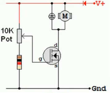
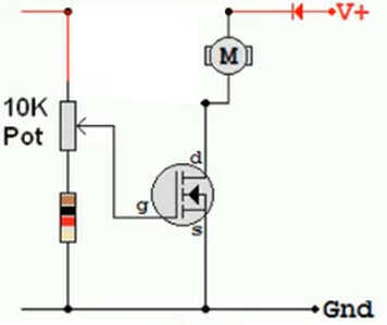
In this 2nd video the following scheme is used:
If I’m right the symbol left to the motor stands for a diode.
This setup uses a single voltage source.
In Bill’s example, as I understand it, the potmeter and Gate are separately fed by Arduino’s 5V.
- In that case would below scheme be a right representation?
- If so can it be that a diode is only required in case of a single power source and otherwise the resistor will sufficiently protect against back current?
Wow, thanks Mike, this forum goes fast!
Good to pick up more terminology.
To me as a novice you’re absolutely right. For my reply @robotbuilder I found some extra insights .. 🙂
Somebody here suggested I should connect the Battery (-) to the Arduino GND. Does that make sense?
Electricity flowing out of a Arduino pin has to flow back again via the ground pin.
As I understand it if the Arduino is being powered from the same 12VDC then to power the Arduino the +v of the battery would be connected to the VIN pin and the -v to the GND pin of the Arduino. In the dronebot example I am assuming a separate voltage supply is being used for the Arduino and the modules and you can see the GND pin on the Arduino is connected to the GND pin on the modules to allow the electricity to flow from the pins into the MOSFET gate and back to the Arduino.
If your main power supply is greater than 12v you will need use a voltage converter to drop it down to a voltage between 7volts and 12 volts so as not to overheat the Arduino voltage regulator.
My practice has been to power the Arduino separately to the motors.
Although some MOSFETS have an inbuilt diode for voltage spike protection I would use a diode between the terminals of the solenoids as added protection.
Remember the PWM pins are not varying the voltage on the pins they are turning them on and off. Applying full voltage to a motor is better than varying the voltage as turning them on/off quickly at different rates will provide max torque at slow speeds. You might hear this on/off as a vibration or hum in the solenoids. I would have to wire one up myself to check that.
Thanks again !
Looking at Bill’s scheme to me it seems everything is connected to GROUND, so it should be fine.
The Arduino is fed with it’s 5V via USB. I use a 12V battery pack to power the Electromagnet. My understanding is that the Arduino-potmeter-MOSFETgate are part of the 5V circuit and MOSFETdrain/source and electromagnet join a the separate 12V circuit.
The electromagnets have no moving parts. However when I’m going to connect more of of these and let them interact with small steel or permanent magnetic objects I imagine backflow therefore is still possible.
- Is there a specific diode that is best to use?
- I assume it should be placed between MOSFET V- and the Electromagnet ?
After taking a deep breath today I powered the setup with a single electromagnet. It works!! No flames, no overheating, the virtual monitor kindly displays the potmeter settings, the EM reacts correspondingly.
As you said the EM resonates over the full scale with increasing tone frequency.
- Are there alternative setups that can separately control the 12V circuit but without PWM?
@risto Always connect a protection diode across a motor, relay coil, or electro magnet.
The diode's cathode connects to the positive power voltage side of the coil and the anode goes to the driven side of the coil (in this case the MOSFET drain).
A 1N4002 will work fine for this purpose.

