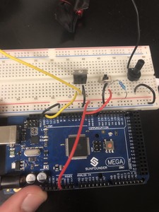
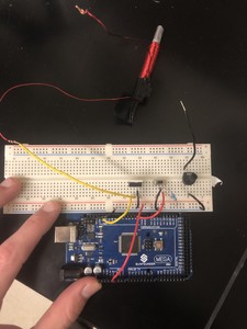
Hi everyone, my knowledge of arduino isn't particularly advanced so this may be a much easier fix than I anticipate. I am currently working on a project that utilizes electromagnets which are turned on/off through a switch that is triggering a voltage output on a separate pin allowing my Mosfet/transistor to open. This allows my high amperage line to run through my electromagnet without frying my circuitry. We have also interfaced it with a variable resistor to have manual control of the current load going into the electromagnet. I got my idea to run it this way off of the dronebotworkshop youtube:
. This can be seen around the 18-25 minute mark. Instead of a lamp I have an electromagnet, the 6vDC is a powersource capable of outputting multiple amps. I have set up my circuit in the same fashion and used the code provided in the video, granted I deleted the last two lines so when I open my switch it will always output my voltage to the gate of the mosfet and vise versa. It works fantastic with just one! My question is: What is the best way to change the code to allow for 6 different switches to trigger 6 different mosfets to open, ie. switch 1 turns on/off electromagnet 1, switch 2 turns on/off electromagnet 2 and so on. I have read a lot about using 1 pin and multiple push buttons to trigger outputs on several other pins, however I'm not sure if this is the best option to keep it simple in terms of code. Is it possible to use 6 pins each attached to 1 switch to be used as analog inputs, each switch triggering a different outpin? Ie. swicth attached to pin 3 triggers output on pin 13, switch attached to pin 4 triggers output on pin12 and so on. We are using an arduino mega so the amount of pins isn't an issue I'm just honestly not sure where to begin in terms of amending the code. I hope this makes sense! Please let me know of any questions you all have for me and I will get to them swiftly! Thanks a bunch!
Hi Nick (and welcome to the forum)
That video looks very familiar LOL!
I just want to be sure that I understand your question correctly, I'm a little confused as you mention the experiment with a lamp that uses a BJT but you seem to be actually talking about the experiment with the MOSFET and the motor, which is a bit later in the video. And also, you speak of using analog inputs for eth switches, when digital ones make more sense (although you CAN use the Arduino Analog inputs as digital ones).
If I understand correctly you just want to control six electromagnets using six MOSFETs and six pushbutton switches - is that right? If it is then the wiring is quite simple and you would use 12 digital I/O ports, six for switches and six for pushbuttons.
And of course, make sure to add those reverse diodes in the circuit as your electromagnets are inductive loads! Check out the example with the motor for info on that.
As for the code, what do you actually want it to do? Do you just need each switch to toggle it's respective electromagnet on and off, or is there more to it than that?
😎
Bill
"Never trust a computer you can’t throw out a window." — Steve Wozniak
Hi Bill,
Thanks for the quick reply! To answer your question, yes precisely, I want each switch to toggle its respective electromagnet on/off. In terms of when I referred to the video I was referring to the part with the lamp and 6VDC. We are however adding a potentiometer where we only use 2 ports so it acts as a variable resistor. When the electromagnets are ON the amount of current running through them is controllable, therefore the magnetic force created is controllable...I have tested with one and it worked great, just needed a smaller variable resistance to modulate the current better. I'm not the best at explaining things so I have attached a picture of the circuit I made and the code I used for just a single electromagnet to help better explain. In the picture below one end of our power source attaches to the electromagnet(red wire) and the other to the variable resistance (black wire).. Im missing a resistor in front of the gate on the mosfet like in the video but will add one shortly! Wiring is not an issue, I have a pretty solid grasp on wiring just am curious about the code.
I have also attached the code I used above for the single magnet. I was thinking I could change it to be something along the lines of this for the 6 magnet set up:
Sorry for the picture spam, I think this will help explain it better however! I can go down a rabbit hole for hours on these projects due to really small code inconsistencies because I'm not the best at coding so I appreciate you taking the time to help me out!


