Hi, It was very interesting to watch the servo control using the PCA9685 as I want to operate servos for Point turnouts on a model Railway prob using a Mega as have lots of Data pins, the problem I find as I have only the basic skills of programming I would like to use the Data pins instead of the A0 - A3 as cant use A4,A5 for the Input using a switch, I would be most grateful for help with changing code to do this...
Hi @john40131
Since you "talk" from an Arduino to the PCA9685 on an I2C bus, using only 2 digital pins (+ ground and 5V), I guess you are dealing here with the "command circuitry", looking for something different than 1 potentiometer per servo.
So some questions i'm wondering about are :
- where will the decisions to move the servos come from ?
- is it a manual or automated process (like responding to feedback from a sensor) ?
- will the servos have preset positions to move to ?
I think numerous different solutions could be used depending on the above.
Eric
Hi Eric, I think initially the decision to move servo's which will have Piano wire connected from the arm to the points, at some stage in the future as I get more advanced I will try and use JMRi... it does get more complicated as when points move signals will change but that is covered below...
The Manual / Automatic sinario could be both as I do intend to put IR avoidance sensors under tracks for Block detection ...
The Servos will probably have an arc from 0 deg say 10 oclock to 60 deg at 2 oclock this will allow the arm to flex the Piano wire through a hole in baseboard to move point' as Piano wire will have some give the angle not critical, on my mounts I have also got a basic mount for servo only or 2 Micro switches so arm switches mcroswitch, all designed a 3D printed by myself...
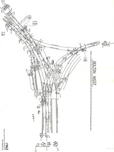
I alreadfy sent a picture of Bolton station that i am relicating...
Regards John
Hi @john40131 !
I have seen your photo from this other thread and I think I understand ? better what you want to achieve now.
I was misreading your initial post and wondering about why you would use analog pins for "command input" while you are actually asking about digital pins...
So, what (I think) I understand is that :
- you'll end up with quite a number of micro-servos which will each manipulate a railway switch, transmitting movement ("actuating") through piano wire to the physical devices
- you will have "human/manual" decisions to flip a railway switch from position A to B, but you will also have some "automated decisions" coming from sensor-detected conditions
My first tought here is that for the "output side", going to the servos, which could be quite numerous, the PCA9685 is a good choice since you only need a single I2C bus to communicate from your Arduino to multiple PCA9685's, all on the same I2C bus, as long as they have different I2C addresses : you will only need 2 pins (SCL+SDA) on the Arduino (+GND and VCC) to send movement requests to any number of servos, thanks to the PCA's on the common I2C bus.
For the "command input side", having a number of sensors + some kind of manual switches, to avoid running out of digital input pins on the Arduino, you can also multiplexing all these inputs with I2C GPIO expanders like the PCF8574 (which can be used for logic level output as well as input). I think this video will give you a good idea of what can be done with it :
I just ordered some of these on amazon to play with, so if you need some programming help don't hesitate to reach me...one or two weeks from now i should have received them and i should have had a bit of time to do some testing...
About your pairs of micro-switches that i saw on the photo : I think you plan to use them to limit the movement of your micro-servos, but that will add a significant number of inputs to your setup (2x Nb.servos) : maybe it would be easier to memorize in some way the 2 positions you need for each servo ?
Eric
Hi ZeFerby, Thanks very much for commects yes you are more or less correct as to what I want to do I will have a look at the PCA8574 and the reason for changing from Analog inputs is I am limited to number of inputs also only want to move servo about 60deg to change points there is a piece of 0.8mm piano wire in the arm which goes through a 3mm hole in mount .. through a larged hole in baseboard and there is a small hole in the change lever of point so the piano wire will rock for left to right and therefore change point ... you can do different ways but this way you dont see the point motor as under board...also the micro switches which I may or maynot need are for rail polarity switching so if you think of a LH point ... straight ahead Frog is Blue but when you switch point the Red rail requires the frog to change to Red as per my picture... if you look at the Scissor crossing which I am also making from parts is a lot more complex...
Ooooh I totally missed the "power through the rails" requirement...
Anyway, for railway switching I don't see where analog would be required ? If I did not miss some other issue, I see mostly binary logic a.k.a. digital in your requirements :
- switch a crossing either left or right
- toggle a crossing based on a falling or rising signal on a button press
- read a detection sensor as either active or inactive
- turn a led on or off
The only thing I can think of, which would be analog-typed, is speed control, but my knowledge of railway modeling technique is non-existent, so I'll shut up now...
By the way, being french I'm usually the one called Frog...I had to google to meet my railway homonymous ! ?
Eric
Model railways today is very complicated or it can be, DC systems just run on 12 DC variable from a controller therefore you can only run 1 train on the same line.
DCC is a totally kettle of fish, which is what I am using its basically a 15 AC (or the DCC signal) which I built an Arduino Uno and Motor shield and "Base Station" from Github, I also have a Hornby Select Controller you can find the workings of that on Horby web site, so the tracks are run via decoders on trains and the controller has to talk to any train on the track via PWM from the controller you can run as many trains as you like on the same track but each one is controlled with an access code "03" is the start code for loco's so you switch to program mode when you first put a new loco on track and set the access code, so when running on points or crossovers or say a reversing loop you have to isolate sections so you can change the polarity of the line so if you look at the scissor crossing "Red" is N0 1 AC line and "Blue" is No 2 AC line so when you switch points you have to make sure polarity is correct or you will get a short... so on my 4 way crossing all the Diamond crossover frogs have to be isolated from the rest of the track and polarity switched depending on which way you are going...
The Pic shows the simulation of the scissor crossing the LEDS would be the track connections and the 2 x 12 volts would be the DCC signal...
John
...I'm now on another google cruise, this time about DCC...with a stop to get some aspirin !
Eric
Ok John, I get it !
Eric
I just received several PCF8574T I2C IO Expander boards (this model is from french Amzon and actually the PCB is printed "WaveShare" at the back : https://www.amazon.fr/gp/product/B07B46TY8K ).
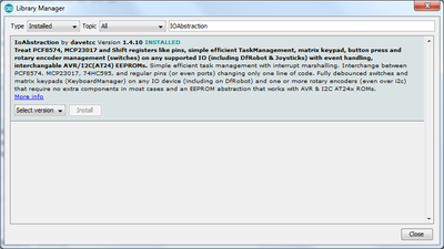
I also came accross an interesting library for management of a large number of inputs/outputs, able to present in a uniform "Arduino-pin way" all the pins from an Arduino itself plus those of multiple I2C expanders like above, or shift registers as well (but i think it is limited to only 2 different kinds at a time, not the 3 kinds Arduino+I2C+ShiftRegs at the same time). It also features switch/encoder and EEPROM management and a TaskManager which enables to program in an "event-driven" way and to schedule one-time or recurring tasks as well.
Since I expect you'll have a rather large number of I/O ports to monitor, maybe that could help you ?
Here is the library :
The web site is : https://www.thecoderscorner.com/products/arduino-libraries/io-abstraction/
I've been checking the source code of the lib, which looks quite nice, but I have not done any test yet...
Eric
Just checked out your link for the module but I dont think thats what I need the PCA9685 has 3 pins for each servo and 12 channels on one board and you can daisy chain them and just alter the address on the board for each one...
John
No no no John, the shift registers or the I2C IO expanders like PCF8574 are more for general purpose I/O like getting alerts from numerous sensors or sending digital output to numerous LEDs, NOT for controlling servos which is, as you wrote, the job for the PCA9685.
So i see these 2 kinds of gizmos as complementary, based on my assumption that you'll have both numerous servos controlled by PCA9685's, and also numerous detection sensors +switches, and LEDs for traffic signals ?
And they are both manageable on the I2C bus (PCA9685 + PCF8574) (but then when a number of I2C slaves are on the same I2C bus, the pull-ups for the SDA/SCL lines has to be checked or I2C switches used to split the I2C bus)
Eric
To clarify what I mean : with only 2 pins for I2C SDA/SCL (+GND+VCC), you can control for example :
Nx PCA9685 - with up to 16 servos on each
NxPCF8574 - with up to 8 inputs(switches, sensors)/outputs (Leds, etc) on each
But a PCF8574 also needs an available interrupt-enabled pin on the Arduino, so if you need more than 2 of them you'll have to use a Mega, because the Uno only has pins 2 and 3 available for interrupts
Eric
I dont think I will put more than 32 point servos on 2 PCA9685, If i need more somewere on layout will just do same again and connect up to another Mimic panel with switches for switching servos, I just need experiment to change from Bill's original video using potentiometers, I just want to use switches that way I can get up to 32 inputs and set servo angle to approx 60deg...
I did a silly thing when I first tried thinking PCA9685 worked on 12 volts, ... strange why doesnt it work ... ooopppsss works on 5 volts on PCA board ...LOL
John


