From what I can see, there are three ways to power an Arduino. 1) The USB connector. 2) An external barrel jack, which not all boards have. 3) The vin pin. Except for the USB connection all of these requires more then 5 volts. All of them feed power through the on board regulator limiting how much power external shields can use.
How can one power a Nano and shields from a single 5 volt source without going through the on board regulator? I was thinking to use the vin pin but then the +5v pin is not 5 volts.
Normally the USB. I think only the UNO has a jack. The VCC pin is an output pin but can be used to provide a small amount of power, nowhere near as much as the USB.
It's all in the Datasheets that you can download on the Arduino.cc site. Your statement about 'more than 5V is incorrect except for the barrel jack. USB and VCC are both 5V only.
When you read the datasheet, you will see what the VCC pin is limited to vs the USB. Most of my setups are 12V to LM2596 down to about 7 then to LVR like a Pololu or similar. The output of the 5V VR is wired to the power pins of the USB jack of which I have many styles and handfuls.
EDIT: Some VCC pins may be connected to a VR.
First computer 1959. Retired from my own computer company 2004.
Hardware - Expert in 1401, and 360, fairly knowledge in PC plus numerous MPU's and MCU's
Major Languages - Machine language, 360 Macro Assembler, Intel Assembler, PL/I and PL1, Pascal, Basic, C plus numerous job control and scripting languages.
Sure you can learn to be a programmer, it will take the same amount of time for me to learn to be a Doctor.
@zander Thanks for the reply.
I have the datasheet and pin out diagrams for the all the boards that I have. For my projects I have several shields that stack on top. I do not want to load the Nano's regulator powering all the shields. Was hoping that I could use the vin pin to power Nano and shields with 5 volts.
Per the datasheet;
Power
Mini-B USB connection
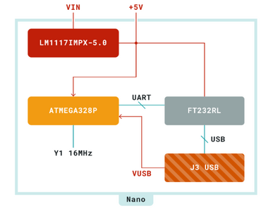
6-20V unregulated external power supply (pin 30)
5V regulated external power supply (pin 27)
5 volts on the vin pin goes through a low dropout regulator and gives less than 5 volts to the processor.
@therabi If you look at the next page, you will see the Power Tree diagram. It clearly shows the VIN pin is limited to 800mA. Not sure what the USB limit is, but I would expect it to be more. 800mA is still a lot, but how many NANOs have been fried by putting the tiny connector on the wrong pin? I like to play it safe and use the USB. Good luck.
First computer 1959. Retired from my own computer company 2004.
Hardware - Expert in 1401, and 360, fairly knowledge in PC plus numerous MPU's and MCU's
Major Languages - Machine language, 360 Macro Assembler, Intel Assembler, PL/I and PL1, Pascal, Basic, C plus numerous job control and scripting languages.
Sure you can learn to be a programmer, it will take the same amount of time for me to learn to be a Doctor.
Hi @therabi,
To start with, please understand I have only glanced at the Nano schematic, and hence I may have missed something ... so my comment is only a first impression and anything you do is at your risk.
----------------
The Arduino doc page https://docs.arduino.cc/learn/electronics/power-pins#3v35v-pin
discusses the alternative, including:
Powering via the 3V3/5V pin*
*Powering your board via the 3V3/5V pins is not recommended, as it can damage your board's voltage regulator. Read more here.
And if you click the "here" link ...it explains that the regulator may be damaged if it's output voltage is higher than its input ... a 'classic' vulnerability of many linear regulator chips.
-------
Looking at the schematic suggested two approaches to consider:
I think the danger discussed in the above referenced pages is likely to be a problem if you have a circuit connected to the input of the regulator, which can conduct a significant current to ground. One approach to consider (but that I HAVE NOT tested), could be to link Vin and 5V pins, and drive both from a 5V source .. hence there should be no current flow through the regulator.
However, in practice, maybe just ensuring Vin is not connected to anything would also suffice.
-----
Alternatively, the Nano is clearly designed to be powered by the USB socket ... and on the schematic,
https://www.arduino.cc/en/uploads/Main/Arduino_Nano-Rev3.2-SCH.pdf
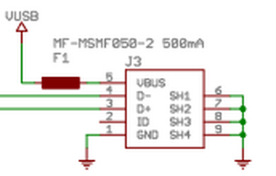
the 5V USB input goes into the VBUS pin and through what I presume to be a 500mA resettable 'fuse'
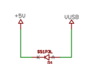
To 'VBUS', which in turn goes through a diode, to the +5V line for the whole board.
Clearly the fuse and the diode provide some current limiting and protection against reverse polarity, but otherwise seem to come very close to powering the 5V line directly, from which you can draw your own conclusions.
This also suggests the possibility of powering 'directly' from your 5V supply, via a USB plug, just connecting the +5V and ground pins. Of course, if you need to connect to the USB for downloading and debugging software from your PC, you may need to get a little creative about the connection strategy ...this should include making sure ground connections to both the PC and the power supply, so that they are all at the same ground potential.
---------------
MAKE SURE you do NOT feed 5V power back into your PC ... accidentally applying a voltage of more than 5V to a PC USB socket can destroy your PC!
-----------
Hope this is helpful ... I have suggested where to look for answers, but if you have any doubts, please remember that mistakes and oversights can break electronics.
Take care and good luck, Dave
@davee, Thanks for the reply and links.
I need to figure out how to explain what I am trying to do. I may have to add a jumper to the USB power. I have USB power blocker to protect the laptop I am using.
Hi @therabi,
Good to hear you have a power blocker to save your laptop.. that is (usually) the most expensive mistake to make!
Obviously, I can't physically see and check your wiring, so I have to be cautious in what I suggest, but clearly providing separate wired feeds to your shields should reduce the current flow through the Nano. Supplying a large current to shields from a Nano or similar was not envisaged in the 'shield' concept.
Personally, if I was doing what I imagine you are doing, I think I would also supply 5V directly to the Nano, either via the 5V pin or the USB pin, try to minimise the risk of the onboard regulator being subjected to a reverse current flow, and accept any risks as part of the cost of developing something new ... but this is your project and your decision.
Of course, some shields only draw a small current, so the importance of this depends on this factor as well.
Don't forget that any current flow into (say) the 5V input of a Nano or shield must also return via the 0V/Gnd connections, so think of each significant current load as being on a loop from the power source terminal, and follow it round back to the 0V/Gnd terminal of the supply, ensuring it is adequate at all points around the loop.
There is a considerable 'art' to designing optimal power and grounding schemes which is difficult to adequately convey ... the good news is that countless designs have worked in spite of breaking the 'rules' ... the bad news is that a considerable number of designs (particularly for production) have needed late redesigns and modifications because not enough care was taken. So try not to be too scared, but be prepared to read as much as you can on the subject and to change a scheme that doesn't work as you hoped.
As for using the USB input for power input, the presence of a 500mA 'fuse' that I discussed previously, suggests the total current into the Nano board, including any powering shields etc. drawing current from the Nano should be kept well below 500mA. Personally, I think this current level is also a fair guide line to aim for when powering via Vin or +5V pins as well, given the general constraints, although it is plausible that it will withstand considerably higher currents.
Best wishes and good luck, Dave
@davee Thanks for all the help.
Thanks to everyone that replied.
Posting this so that anyone else may find it helpful.
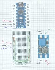
I am using prototyping boards that were designed for use with the Mega 2560. I have come down to two options.
First is with 5 volts coming in send 5 volts to the Nano 5 volt pin and directly to the 5 volt pin on the prototype board. Do not connect the VIN pins together. This is not recommended as show above.
Second is to sent 5 volts to the 5 volt pin on the prototype board. Use a boost converter set to 6 volts to send power to the VIN pin on the Nano. Do not connect the Nano 5V or VIN pins to the prototype board.
As for myself the second is the one that I will be going with.
@therabi I am unclear on what the 'prototype board' is. Also unclear about the rest of it. A diagram would help a lot.
First computer 1959. Retired from my own computer company 2004.
Hardware - Expert in 1401, and 360, fairly knowledge in PC plus numerous MPU's and MCU's
Major Languages - Machine language, 360 Macro Assembler, Intel Assembler, PL/I and PL1, Pascal, Basic, C plus numerous job control and scripting languages.
Sure you can learn to be a programmer, it will take the same amount of time for me to learn to be a Doctor.
@zander Hope this helps.
Prototyping boards are perf-boards that have headers to fit a given development boards. It can be used to make one time circuit boards.
The power supply for this is from the 5Vsb from an ATX power supply. The VIN pin on the Nano needs more than 5 volts applied to give 5 volts to the processor. By separating the power to the 5V and VIN pins on prototype board from the Nano's pins it will prevent overloading the Nano's regulator.
@therabi Ok, now I understand.
Not that I need to, but I still don't understand all the messing with 5V and different pins but I wish you good luck.
First computer 1959. Retired from my own computer company 2004.
Hardware - Expert in 1401, and 360, fairly knowledge in PC plus numerous MPU's and MCU's
Major Languages - Machine language, 360 Macro Assembler, Intel Assembler, PL/I and PL1, Pascal, Basic, C plus numerous job control and scripting languages.
Sure you can learn to be a programmer, it will take the same amount of time for me to learn to be a Doctor.
@therabi No problem, it's my problem, I am on the spectrum and sometimes have difficulty understanding other people.
First computer 1959. Retired from my own computer company 2004.
Hardware - Expert in 1401, and 360, fairly knowledge in PC plus numerous MPU's and MCU's
Major Languages - Machine language, 360 Macro Assembler, Intel Assembler, PL/I and PL1, Pascal, Basic, C plus numerous job control and scripting languages.
Sure you can learn to be a programmer, it will take the same amount of time for me to learn to be a Doctor.


