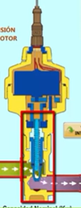
I have a step motor that drives a screw linked to a conical flow control valve. To control the valve position the first action is to move the crew till the valve is closed, with enough steps to assure the close position is reached regardless the initial position. This action obligues the step motor to work against a fixed position (valve closed) and its operational sound changes and surely there are changes in the coil current.
Volt of step motor is 12 VDC. Coil resistance are 106 ohm each so the expected current is 113 mA
Due the above figures, could it be hard to meassure the increment in mA due the "blocage" of the screw and the stop the step motor?
Your help will be apprecited
Hi Riolea, welcome to the Dronebot forum..
First of all, your question "could it be hard to measure the increment in mA due to the "Blocage" of the screw and the stop of the step motor"
I'm not quite sure what you'd be measuring, but yes, you could measure the current using a ACS712 current sensor, but As an old control valve specialist, I would recommend using an encoder, linear, or rotary, depending on what type of valve stem movement you have to deal with, to measure the travel distance from close position to full open.. This feedback would be necessary to properly position the valve for proportional flow characteristics. perhaps a photo of what your trying to do would help us to make a better suggestion. In my work life (retired now), I specified control valves with PID control "Smart positioners on various types of control valves. This sounds like an interesting project..looking forward to seeing how you progress..
Merry Christmas, and a happy new year.
regards,
LouisR
LouisR
Have you considered Trinamic stepper controllers ?
https://www.trinamic.com/technology/motor-control-technology/stallguard-and-coolstep/
Anything seems possible when you don't know what you're talking about.
Dear LuisR. Thanks for your reply. The valve I am talking about is shown the picture bellow
You can see the stepper motor on top an the conical valve at the botom, that closes the flow
The stepper motor operates ar 12 V, the coil resistance is 106 ohms and the current is 113 mA
I am not sure about the increse in the current value when the valve is closed and the stepper motor continues receiving operation order, enough to meassure and evaluate the situation to stop the stepper motor.
As you can see there is no pace to install any element to detect the valve is closed.
Usual action is to allow the stepper motor receiving motion order wothout damaging the valve, but it is something I am not happy.
I look forward for your comments
Best regards
Ricardo Olea
@Riolea, I think @will has come up with a good possible solution..check out this web site I found, and attached a word file doc for your convenience to peruse...Yes, you have a very unusual valve configuration, but then I've see many different types in my years...looking forward to seeing how this works out for you.. and thanks to @Will for the information..Merry Christmas and a happy new year to all...
Regards,
LouisR
LouisR

