Greetings, all!
I am attempting to use a 24VDC motor (with an internal encoder..Model IG42 robotics motor), a relay, an (ON)-OFF-(ON) switch, an L298N H-Bridge module and an Arduino Mega for a flight simulator project I’m working on and need some coding/scripting help. I’m not certain if this is the proper place to request help.
The goal is to replicate an aircraft electric trim switch to stabilize up/down elevator movement. One of the switch’s ON positions will spin the motor clockwise and the other ON position will spin the motor counterclockwise, simulating up and down nose (elevator) movement. A sprocket will then be attached to a chain-driven wheel which turns the trim wheels.
I know I need to define the relay, motor pins, both on positions (and think I can use a standard PULLUP call for the ‘OFF’ position of the switch in pin mode), as well as a limit (MAP function) at both ends of the limits (255 and -255??) but am not entirely sure.
Is this possible and if so, how would my coding look like?
I would truly appreciate any guidance on this subject.
Jay
an (ON)-OFF-(ON) switch
Are we talking about a toggle switch?
Not sure where the relay comes into the equation?
Using two toggle switches this is how I manually controlled each motor on a robot base.
Thank you for the reply.
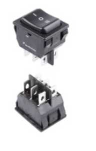
Sorry…it’s actually a rocker switch.
Thevrelay is needed because it operates on 24VDC.
Greetings, all!
I am attempting to use a 24VDC motor (with an internal encoder..Model IG42 robotics motor), a relay, an (ON)-OFF-(ON) switch, an L298N H-Bridge module and an Arduino Mega for a flight simulator project I’m working on and need some coding/scripting help. I’m not certain if this is the proper place to request help.
The goal is to replicate an aircraft electric trim switch to stabilize up/down elevator movement. One of the switch’s ON positions will spin the motor clockwise and the other ON position will spin the motor counterclockwise, simulating up and down nose (elevator) movement. A sprocket will then be attached to a chain-driven wheel which turns the trim wheels.
I know I need to define the relay, motor pins, both on positions (and think I can use a standard PULLUP call for the ‘OFF’ position of the switch in pin mode), as well as a limit (MAP function) at both ends of the limits (255 and -255??) but am not entirely sure.
It's a little hard to visualize what you're attempting to do. Will the "trim" function be on/off or continuous ? If it's to be continuous to find a balance point, then a potentiometer would probably be a better starting layout. Just rotate the pot to the desired angle and and have the motor move to the correct angle.
It sounds like a servo would be a better choice than a DC motor, and L298N driver. But that assumes that you don't have to match an existing flight control. How much design freedom do you have ?
Also, you should consider using a MOSFET instead of a relay: longer life, way less heat and power, much cheaper, etc 🙂
Anything seems possible when you don't know what you're talking about.
The trim function is activated by the switch (either up or down, as needed).
Ithe project needs to have this IG42 motor as it will drive a chain assembly which will be used in a home cockpit. No other alternatives will work here due to torque and housing requirements.
it’s actually a rocker switch.
The relay is needed because it operates on 24VDC.
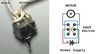
Double Pole double throw (DPDT) rocker switch is the same thing just a different handle
My motors were 24vdc you only need a switch rated to handle the voltage/ampere of the motor.
It sounds doable, but a couple questions. Is the relay a double throw like your rocker switch? The relay purpose is to handle the 24V and I assume more current than just the rocker sw can handle? Why do you need a mega, it sounds like even the tiniest arduino would work. As @will pointed out you could substitute a mosfet for the relay but both will work. If this sounds way off, maybe we need to see a wiring/circuit diagram.
First computer 1959. Retired from my own computer company 2004.
Hardware - Expert in 1401, and 360, fairly knowledge in PC plus numerous MPU's and MCU's
Major Languages - Machine language, 360 Macro Assembler, Intel Assembler, PL/I and PL1, Pascal, Basic, C plus numerous job control and scripting languages.
Sure you can learn to be a programmer, it will take the same amount of time for me to learn to be a Doctor.
The trim function is activated by the switch (either up or down, as needed).
So I assume then that you'll press and hold the switch down on the "raise" to raise the elevator or press the "lower" side of the rocker to lower the elevator (or the opposite, not sure which orientation is correct).
Ithe project needs to have this IG42 motor as it will drive a chain assembly which will be used in a home cockpit. No other alternatives will work here due to torque and housing requirements.
OK, you've said that the motor has a built-in encoder, so you'd need your sketch to start off by homing the motor to some known point (i.e. zero the motor).
Let's suppose that q is the number of "clicks" that the motor has to turn to move +/- 1 degree of trim and that (float) p marks the current motor positioning (in "clicks"
Then, while p is still in a valid range:
While the rocker is pressed "raise" then rotate the motor q turns; p += q;
While the rocker is pressed "lower" then rotate the motor -q turns p -= q;
When the rocker isn't pressed, leave motor as is.
Note that you'll need to convert +maxTrim and - maxTrim to clicks and ensure that the resulting p is always in range.
You might still be better off to replace the L298N with MOSFET drivers and a couple of diodes to prevent back feeding. One circuit for forwards and one circuit for backwards.
Anything seems possible when you don't know what you're talking about.
I am attempting to use a 24VDC motor (with an internal encoder..Model IG42 robotics motor), a relay, an (ON)-OFF-(ON) switch, an L298N H-Bridge module and an Arduino Mega for a flight simulator project I’m working on and need some coding/scripting help. I’m not certain if this is the proper place to request help.
There are people here that understand electronics and programming but without a complete description of the flight simulator it is hard to know what to offer beyond what Will has suggested. I assume the Mega does more than control the trimmers. Code depends on the actual hardware you are using not on what we might imagine you are using. I have googled Arduino Mega based flight simulators to get some idea. Your trims are real I assume but not functional as in not being in a real aircraft. You want a relay to control 24v from the 5volt output of the Arduino. So is the rocker switch connected as input to the Mega?
Thank you, all, for the replies and interest!!
I’m planning on using the Mega because it is a part of a set of four (4) that were given to me as a gift from a dear friend. Also, in future projects, the many pins on the Mega will be very useful in the entire project to operate other instruments and gauges as opposed to several ‘smaller’ boards scattered here-and-there.
As far as my DC motor with the onboard encoder is concerned, I had not planned on using the encoder, which has four (4) separate wires and a separate connector in addition to the two (2) power wires (red and black), also with its own connector. I do not require a ‘zero’ or position sensing capability for this application. This motor was also a very welcomed gift and works flawlessly when the polarity is swapped, hence my thought for using the L298N module…simple and easy to code.
Today, I will be experimenting with the L298N coding seen on the Workshop’s main webpage as well as some relay coding. There will be some cutting, pasting and mashing-up of the codes for both and am now convinced this project can be done.
Plainly-speaking, I just need one (1) ON switch to move the motor forward and the other ON switch to move the motor backward—nothing else. For all intents and purposes, my operating trim wheels will just be for effect. Down-the-road, I will be investigating using separate servos or steppers to move the two (2) trim position indicators (Captain’s and First Officer’s side). These trim indicators will be interfaced and will operate in concert with the flight simulator’s internal data references and, at that point, WILL be included with the trim wheel coding and operation. I neglected to say that these are OEM parts from a retired airliner. Accuracy and authenticity are paramount.
Again, my many thanks for the replies and suggestions. It is very much appreciated by this relative newbie.
Jay


