@frogandtoad I used the statement. It is actually a pull down resistor.
Sorry for another question...
What if I use just a piece of normal wire instead of a resistor in the circuit? What property does the resistor has for the 'pull down' job?
You see, I am a slow learner. And I need to understand the basics clearly.
What property does the resistor has for the 'pull down' job?
It has a known resistance to the flow of electrons (measured in amps) just like a narrow pipe reduces the flow of water. It also produces a pressure drop (measured in voltage) just as the water pressure between the two connections of a tap (faucet) and thus water flow will vary as you turn the tap on and off. A normal piece of wire has some resistance but for practical purposes can be considered to have no resistance compared with the effect of other components on the flow of electrons.
You would have a direct short to ground when you pressed the button.
Then, is it pull up resistor or pull down resistor?
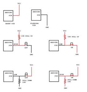
The resistor is in a pull-down position (connected to ground). Pin 2 (buttonPin) reads 0v (LOW) across the resistor when the button is not presses. The pin reads 5v (HIGH) across the resistor when you press the button.
ZoolanderMicro, where small ideas are a big deal
Perhaps I didn't fully answer your question:
You connect the resistor from the input pin to the ground (0 volt) or the supply (5 volt) and the resistor will limit the current flow. The input pin will be pulled to a value of 5 volt (if connected to the supply via the resistor) or pulled to a value of 0 volt (if connected to the ground via a resistor).
If the pin is connected to the ground via a resistor then pin will be LOW and if the switch (that connects wires) then shorts it to the supply the pin will go HIGH.
If the pin is connected to the supply via a resistor then pin will be HIGH and if the switch (that connects wires) then shorts it to the ground the pin will go LOW.
Just noticed zoolandermicro gave an explanation as well.
I am also slow learner. And I also need to understand the basics clearly until I hopefully "get it".
@zoolandermicro Thank you so much. I needed such an explanation 😀
Now things are making sense.
@frogandtoad I used the statement. It is actually a pull down resistor.
Excellent!
Learning how to employ these statements strategically is a great tool to debug your code when troubleshooting problems.
@robotbuilder In this case, the resistor pulls the switch to the ground. But if I connect the resistor to switch and to the 5V connection, then the resistor will pull up the switch. Will it cause any fault in the circuit?
Another question:- The main role played by the resistor is applied only when the circuit is off or open, right?
You would have a direct short to ground when you pressed the button.
By this, you actually mean that there will be a short circuit when the switch is off. When the switch is on, the supply will provide 5V and light the LED. But after switching it off, there will be a short circuit. Right?
Maybe this will help? Hope I drew it correctly!
Right click image choose Open Link to New Window
@robotbuilder Thank you so very much!!!!!! 😀
I have finally understood the whole concept. I don't find words to thank you.
That's a good example!
For a digital (technical behind the scenes) example, take a look at the following page about half way down:
Cheers.
@frogandtoad Thank you for the link. It helped, but I actually don't know anything about logic gates. Anyway, thanks for the link again. 😀
These topics come under the subject of "Digital Electronics" of Physics, right?

