I plan to use an Arduino Mega 2560 to drive 14 G3MB-202P SSRs (5v input). I've read that it is a good idea to keep the per-pin Arduino output current down to about 20 ma and perhaps the total output current below 200 ma.
The load per SSR will be around 30 watts at 120VAC.
So... I don't have the SSRs yet. They will consist of 2 banks of 8. And it isn't clear what input current per SSR is required with the input resistor type. Specs do say 440 ohm input and 4 vdc turn on voltage but that could be for the individual SSR device rather than the banked configuration.
I'm wondering whether I could reduce the current per output to 10 or 12 ma and still have the SSRs turn on reliably and not harm the Arduino.
Or should I plan to use mosfets or transistors to drive the SSRs?
Thank you
An additional note: I just discovered that these SSR modules may be purchased as High Trigger or Low Trigger. The SSR boards I have on order are Low Triggered. So 0v to 2.5 v turns the SSR on. 3.3v to 5v turns it off.
My understanding is that the Arduino can sink or source the same amount of current. So maybe High or Low Triggering doesn't make a difference insofar as drive current is concerned. (??)
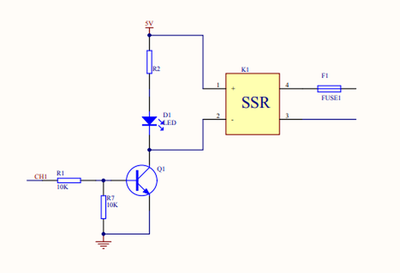
I found a diagram of the SSR wiring from the Sainsmart version of an 8 SSR board. Hopefully it is typical.
However, this is a High Trigger arrangement. It appears the current is greatly limited by a 10k series resistor. And an NPN transistor is used to drive the SSR input.
.5 MA ?? Also, the current to drive the SSR itself does not come from the Arduino Output pin.

