I'm making an attempt to use an RYLR896 module, however it is not working. Any input would be much appreciated.
I have looked at a number of tutorials, both video and text, and have tried to boil it down to a simple proof-of-concept design.
The connections seem quite simple:
Arduino - RYLR896:
3.3v to Vdd
gnd to gnd
Tx to Rx
Rx to Tx
(I'd post a diagram, but I am not seeing an option to upload an image.)
This is my code. It reads a "sensor" (variable resistor.) Distilled from this page:
https://www.electroniclinic.com/sensor-monitoring-using-lora-by-reyax-rylr890-rylr896-and-arduino/
(Note however, I could not get the code as written in the article to work either. I also tried another example which used SoftwareSerial, but couldn't get it to work either.)
Transmitter:
Receiver:
void setup() {
  Serial.begin(115200);
  Serial.print("AT\r\n");
  delay(100);
}

void loop() {
  if (Serial.available()) {
    String rcvdData = Serial.readString();
    Serial.println(rcvdData);
  }
}
Note: I have since realized Strings are not recommended and not needed here, but this should give an idea of what I have done.
Update:
I have attempted to communicate with the RYLR896 using AT commands per this video tutorial:
I get no responses. I reversed the Tx/Rx connections on the Arduino as instructed.
I purchased 2 modules when I started this, and have the same results with both.
I'm beginning to wonder if I have bad modules or bad luck.
The aforementioned video instructed to remove the Tx/Rx connections on the Arduino before uploading a program which I did not do when following the first tutorial (it wasn't mentioned there.) I don't know if that can damage the transceiver modules, but it doesn't seem like it would.
@kevinjones, No, it probably didn't damage the modules by uploading the sketch with the TX and RX connected to the processor. The reason why you need to disconnect the TX and Rx from the processor is because the serial port is busy with trying to load the sketch, and the RYLR896 is trying to establish communications at the same time.. so the conflict will not allow you to upload.. as to the other problem, it's highly unlikely that both units are bad.. most likely something in the sketch isn't right..
One thing I might mention is to make sure that the serial monitor ibaud rat is set to the same baud rate that your sketch is.. I believe in t is 115200 ? check this first..and hopefully someone with more skill in reading and deciphering the AT codes will find the problem..
regards,
LouisR
LouisR
@inst-tech Thanks for the reply.
Per instruction on the tutorial, I reversed the Tx/Rx connections on the Arduino (now Tx on Arduino to Tx on transceiver; Rx on Arduino to Rx on transceiver, through voltage divider,) have baud of the serial monitor set at 115200, and line endings set to “Both NL & CR”. I send the command “AT” expecting “+OK” in return, I get no responses, not even an error. Sending “AT+ADDRESS?” gives no response either.
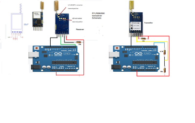
@kevinjones, I found the Site on the web for hooking the Transceivers up, https://create.arduino.cc/projecthub/infoelectorials/project-015-arduino-reyax-rylr896-lora-module-project-8fac15#schematics
and what I noticed is that a connection to the transmitter and receiver are not show in the video you are using.. The connection it to the NRST pint on both receiver and transmitter with a 10k ohm resistor from the 3.3 v pin on Arduino to the 10k, and the other side of the 10k to the NRST pin on the rylr890/ 896
Below is a fritzing schematic of the the hook up...we'll try this and see if it works..
regards,
LouisR
LouisR
@inst-tech Thank you Louis. The last schematic, can you tell me where you found that? Or did you do it yourself?
@kevinjones, Your very welcome kevin... I do the drawings myself using ms Paint and jut google the browser for photos of what i want on the drawing, then right click the image, select copy image, then just paste in into your drawing.. Because Ms_paint has line drawing, and many other features, like text, it's perfect for doing this frizzles schematics, then just save them as PNG files. I store mine in my Arduino user folder, called PNG.
Did the ckt work?...I curious as I may want to do some experimenting on a project i have in mind for home security...
kind regards,
LouisR
LouisR
@inst-tech I won't have time to check it out until Sunday... at the earliest.
@kevinjones...That's fine.. keep us informed of your progress.
Have a great weekend..I'm retired, so everyday's a Saturday...lol
Regards,
LouisR
LouisR
@inst-tech I thought it was everyday is Sunday!
First computer 1959. Retired from my own computer company 2004.
Hardware - Expert in 1401, and 360, fairly knowledge in PC plus numerous MPU's and MCU's
Major Languages - Machine language, 360 Macro Assembler, Intel Assembler, PL/I and PL1, Pascal, Basic, C plus numerous job control and scripting languages.
Sure you can learn to be a programmer, it will take the same amount of time for me to learn to be a Doctor.
Sorry for such a long wait in replying.
I stopped pursuing my attempts to get the RYLR890 working, as I found using SX127x breakout modules much easier to use. (The RYLR890 uses the SX127x, inside a layer of additional processing.):
eg: https://www.ebay.com/itm/362762899146
("RA-01" module:) https://www.ebay.com/itm/183432900897
("RA-02" module - requires external antenna:) https://usa.banggood.com/433MHZ-SX1278-LoRa-Module-433M-10KM-Ra-02-Wireless-Spread-Spectrum-Transmission-Board-2_4G-IPX-Antenna-for-Smart-Home-p-1939044.html?cur_warehouse=CN
Note that the first and the RA-01 modules have a < .1in pitch, so you have to fashion your own header to fit into a .1in form (proto board, etc.) The RA-02 is .1in pitch.
You do not get AT commands using only the SX127x breakout module, but as the commands are all strings, it is a simple matter to encode the strings with your own identifiers if you want to segregate "channels" etc.
It is nicer because you don't really need the extra processing layer the RYLR890 is providing, and programming is simpler (IMO.)
CAVEAT: There are several tutorials on how to set these up using Arduino, however, they appear to be copied from the same tut. I say this because in all of them, they show the Arduino (a 5v device) IO pins connected directly to the SX127x (a 3.3v device) IO pins with no level shifting. They state that you only have to observe powering the SX127x with 3.3v, and and make no mention of level shifting as though it is not necessary. THIS IS NOT TRUE. My experience was it will not work, and in hindsight, I am lucky I didn't damage the SX127x.
If you follow the tuts, just be sure to use a level shifter. Make sure you check the speeds and use one fast enough for the Arduino clock speeds (16 MHZ.) I used a TXB0108 (20 MHZ) which fit the bill and it is working fine. Or use a 3.3v Arduino (Note, I believe the 3.3v Arduinos are only 8 MHZ.)
(You may get away with using resistor voltage dividers for level shifters also, which could reduce your component footprint, but note that will affect speed. I tried it and it seemed to work, but I just played it safe and used the TXB0108. YMMV.)
Here is one of the tuts. It should give everything you need to know regarding wiring (just use a level shifter) and the code:
https://how2electronics.com/interfacing-sx1278-lora-module-with-arduino/
There are several on YouTube as well, just search "SX1278 arduino".
@kevinjones Sounds like you found a solution to your problem you can live with..good job!
Now, on to my project working on a PID control for my robot tank for speed control and object avoidance. It will be necessary for the the robot to be able to not only "see" what is ahead, but to decelerate and take action to avoid the object without stopping, then when clear of the object, accelerate back to normal speed.
The challenge is writing a PID control algorithm.. so far, so good, just need more testing and adjusting proportional, integral, and derivative parameters to act fast enough to make corrective changes on the fly..
This will keep me busy for a looong while...heheh
good luck on your project, and thanks for the heads up on the SX127X board...
kind regards,
LouisR
LouisR
@inst-tech Interesting. I once worked as an instrumentation tech so mentioning PID brings back a lot of memories.


