@will That's 33 OHMS. 31.1 OHMS is close enough in my opinion. The polarity thing is my mistake, sorry.
You aren't getting it. That would mean I have to implement a different physical output jack on my panel for similar functions. One for high resistors, low resistors, high capacitors, low capacitors, etc.. That's a lot of input jacks on the board. the question is very simple: Can two pins share the same breadboard column or physical jack? Can one be turned "OFF" while the other is in use? That's all I need to know.
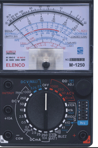
@jeffreyjene Here is a picture of an old style VOM. Notice the resistance ranges and a rotary switch. YES that switch is attaching different parts to a common 'pin'. Today with modern devices my VOM has one setting called AUTO. It does not use the same circuitry at all.
What @will was referring to is 31.1 is nowhere close to 330.
First computer 1959. Retired from my own computer company 2004.
Hardware - Expert in 1401, and 360, fairly knowledge in PC plus numerous MPU's and MCU's
Major Languages - Machine language, 360 Macro Assembler, Intel Assembler, PL/I and PL1, Pascal, Basic, C plus numerous job control and scripting languages.
Sure you can learn to be a programmer, it will take the same amount of time for me to learn to be a Doctor.
@ronalex4203 If I typed 330 ohms somewhere than it was a typo. I understand what you are showing me, this isn't quite the same thing. I want to implement a small panel that has two female pin jacks. You insert a resistor/capacitor and get a reading. It's that simple. I was under the impression that this could be done on the software side with Arduino by "turning on and off" pins by setting them to INPUT or OUTPUT. Obviously there is, as I'm seeing working projects that are using it! I've simply run into a problem that I don't understand. In the examples I saw, the pin at the end of the divider was acting as "ground" without actually being ground.Here's an example: http://electronoobs.com/eng_arduino_tut10.php
Good heavens, this is frustrating! Is there anyone out there who understands what I'm saying or trying to do?
@will That's 33 OHMS. 31.1 OHMS is close enough in my opinion.
Yes, I see my mistake, I read it as 330 mhs instead of 33 ohms... my bad 🙂
Have you thought about using a shift register ? That would allow you to use 3 regular Arduino pins to read and/or write up to 8 external outputs and transfer the pin values in and out as a byte of 8 bit values. Since I don't fully understand what you're trying to do, I can't suggest any specific circuitry but you may want to look at the facility provided by 74HC595 and 74HC165 ICs.
Anything seems possible when you don't know what you're talking about.
@jeffreyjene Ok, I get the gist of it I think, so why are you not just copying the code and wiring diagram you pointed to at http://electronoobs.com/eng_arduino_tut10.php
I did not and will not try to understand the code, but it appears to be what you want. I will tell you it is about 5x more code than need be. Think variables, and sub-routines.
First computer 1959. Retired from my own computer company 2004.
Hardware - Expert in 1401, and 360, fairly knowledge in PC plus numerous MPU's and MCU's
Major Languages - Machine language, 360 Macro Assembler, Intel Assembler, PL/I and PL1, Pascal, Basic, C plus numerous job control and scripting languages.
Sure you can learn to be a programmer, it will take the same amount of time for me to learn to be a Doctor.
@ronalex4203 I am copying it for the most part (for an Arduino Uno) minus the rotary switch implementation. Yes, I agree about the unnecessary code. As a pro Java guy I'm all about re-usability. There should be more in the way of methods with parameters (which I plan to do). The thing is, I want my design to build on that design, including maybe capacitor testing using the same physical jack. Unfortunately his design is where I'm running into the issue with the way-off values when not using a ground on the end of the voltage divider.
@jeffreyjene You might want to include the rotary switch implementation, that's what 'fixes' the multiple connections issue you mentioned earlier, that is the purpose of the rotary selector. In 65 years of electronics I never had a cap tester, just used VOM to check for short until I got a do all tester a couple weeks ago for solid state devices plus R and C.
First computer 1959. Retired from my own computer company 2004.
Hardware - Expert in 1401, and 360, fairly knowledge in PC plus numerous MPU's and MCU's
Major Languages - Machine language, 360 Macro Assembler, Intel Assembler, PL/I and PL1, Pascal, Basic, C plus numerous job control and scripting languages.
Sure you can learn to be a programmer, it will take the same amount of time for me to learn to be a Doctor.
Looking over your sample multi-range diagram ...
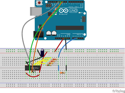
If you used a 74HC595 shift register and connected all of the range resistors to its output pins, tied the other ends of all range resistors together with A0 and one end of the test resistor and connect the other test resistor end to GND, then you could activate each range by sending out a byte from the Arduino with all bits zero except the range you want to test.
That would then set that range resistor HIGH and allow the measurement to be taken at A0 with all other range resistors set off (i.e. zero or LOW).
It also gives you perfect GND for accurate results.
That way, you'd never have to try using Arduino pins for input and output in the same sketch. Furthermore, you'll only need 3 Arduino pins even if you expand the number of ranges.
Also, it would allow you to add more ranges and, since you can piggyback registers, will allow you to add even more than 8 testing points later if needed.
Anything seems possible when you don't know what you're talking about.
@will I like the way this sounds. I'm going to look further into shift registers.
@will Ok, this is what I came up with (sorry, a bit sloppy). The code doesn't really work (I've only coded for the 2K resistor to start), but this is my first time working with these things. Would you mind taking a look?
// Define Connections to 74HC595

// ST_CP pin 12
const int latchPin = 10;
// SH_CP pin 11
const int clockPin = 11;
// DS pin 14
const int dataPin = 12;


//LCD config
#include <Wire.h>
#include <LiquidCrystal_I2C.h>
LiquidCrystal_I2C lcd(0x27,20,4);

int resistancePin= A2;
int v = 0;
int vin= 5;
float vout= 0;

float R1= 0;
float R2= 0;
float buffer= 0;

//Ranging 2K, 20K, 220K, 1M on 74HC595 1-4
int resisterArray[4] = {B10000000, B01000000, B00100000, B00010000};
int testRange = 0;

void setup()
{
  lcd.init();
  lcd.backlight();
  Serial.begin(9600);

  pinMode(resistancePin, OUTPUT);


}

void loop()
{

  ///////////////////-2k-/////////////////////
  //enable the 2K resistor:
  digitalWrite(latchPin, LOW);
  // Shift out the bits
  shiftOut(dataPin, clockPin, MSBFIRST, resisterArray[0]);
  digitalWrite(latchPin, HIGH);

  float R1= 2000;
  v = analogRead(resistancePin);

      buffer = v * vin;
      vout = (buffer)/1024.0;  //in volts
      buffer = (vin/vout) -1;
      R2 = R1 * buffer;

      if (R2 > 2000)
      {
        Serial.println(R2);
        lcd.clear();
        lcd.setCursor(0,0);
        lcd.print(" Increase scale");
        lcd.setCursor(0,1);
        lcd.print("or insert resistor");
        delay(1000);
      }

      if (R2 < 2000)
      {
        Serial.print("----[2K]----");
        Serial.print("\n");
        Serial.print("\n");
        Serial.print("Resistance: ");
        Serial.print(R2);
        Serial.print(" ");
        Serial.print("  ohms");
        Serial.print("\n");

        lcd.clear();
        lcd.setCursor(0,0);
        lcd.print("SCALE:    0 - 2K");
        lcd.setCursor(0,1);
        lcd.print(R2);

        lcd.setCursor(10,1);
        lcd.print("  ohms");
        delay(1000);
      }

}
It looks reasonable, I don't have my notes or pinouts, but the connections to the IC look familiar.
For convenience I'd suggest that you use an int value 'range' (values from 0 to 3) and put the range resistance values in an array similar to resistorArray. That way you can change ranges simply by incrementing or decrementing 'range' and could even auto-select range by incrementing range if R2 > 2000 and range<3.
What part of it isn't working ? If it seems to be powering the wrong resistor, then you may need to switch to LSBFIRST. IIRC, I had some trouble wrapping my head around that.
Anything seems possible when you don't know what you're talking about.
Hi @jeffreyjene,
I have only glanced at your notes but it looks like you are using a shift register to connect/drive your analogue resistors, which intuitively feels wrong.
This may work in certain situations, perhaps when the current flow into or from the shift register is very small, so that the output voltage from the 595 is close to 595 supply voltage, but errors will appear if there are any substantial current flows.
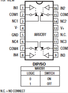
I think you need to look at analogue switches to connect your resistors into the circuit ... these are essentially FETs, so the logic levels do not source or sink any current, although you need to allow for the Ron resistance which will be in series with the resistances you are measuring or using as a reference. (The Ron is the resistance between the 'poles' of a switch when it is closed. The opening page for the 391 mentions a maximum value of 60 Ohms.)
If you haven't seen analogue switches before, an example (chosen at random for discussion purposes only - I haven't looked to see if is suitable for your application), is the MAX 391
There are many other similar-ish devices, each offering a number of switches in a pack in a variety of configurations.
Looking at this example, you will see 4 independent SPST switches, where each switch has two 'pole' connections plus a third connection to be driven by a logic level signal.
I would have expected the 'pole' connections to be used for switching your resistor into position. Your shift register would be used to drive the logic level, thus determining whether that particular switch is open or closed.
-------
I think if you look at your resistance calculation part of your software you will see that vin can be any non-zero value as you first multiply your reading by vin to make vout
buffer = v * vin;
 vout = (buffer)/1024.0;  //in volts
then divide vin by vout.
buffer = (vin/vout) -1;
So this part can be simplified. My previous note tried to explain this.
-------
Hope this suggesion is helpful. Dave
Hi @jeffreyjene,
I have only glanced at your notes but it looks like you are using a shift register to connect/drive your analogue resistors, which intuitively feels wrong.
This may work in certain situations, perhaps when the current flow into or from the shift register is very small, so that the output voltage from the 595 is close to 595 supply voltage, but errors will appear if there are any substantial current flows.
I agree that shift registers are inappropriate for large currents. His base resistor is 2000 ohms, so with a supply voltage of only 5V we're talking about an upper limit of 2.5 mA of current that the IC will need to supply.
Also, note that in normal operation, only one output pin will be HIGH nd all the rest LOW, so that maximum 2.5 mA required current is for the entire device.
With that maximum upper limit, I considered a shift register to be a viable way of supplying power for up to 8 different ranges.
Anything seems possible when you don't know what you're talking about.
Hi @will and @jeffreyjene
I agree that a 595 can readily supply a few milliamps current, but the voltage at that output changes very significantly with current flow (and probably other factors like temperature). These devices are only concerned with delivering output voltages that can be unambiguously differentiated between high and low, not staying close to the rail potentials.
My concern is that the method of determining the resistances based only on the measurement of the voltage at the junction of the two resistors relies on the voltage applied across the resistors being the same as that used by the ADC reference.
The 'high' voltage level output from logic chips like the 595 is only close to the voltage rail when the current flow is almost zero.
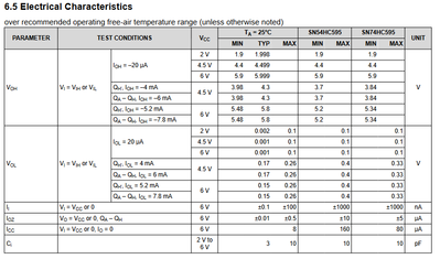
The following table is from the TI data sheet https://www.ti.com/lit/gpn/sn74hc595
A proper analysis would look at the effect on the unknown resistor values over the range of unknown resistors expected to be measured, but for a start, just consider the effect on the voltage applied to the resistors.
Considering VOH with 4.5V supply, this shows that at current of of 20 microamps, the typical voltage drop is only 1mV, "worst case" 100mV. So even the worst case is only about 2% low .. which may be acceptable.
However, when the current increases to 4mA, the voltage drop (at 25 degC temperature) is typically 200mV and "worst case" 520mV. Interestingly, the same voltage drop values are quoted at 6mA, implying the voltage drops may be similar at currents considerably below 4mA.
I hope this information would be of interest to help you understand some of the issues involved, including the possible sources of error.
------------------
Clearly, if the application only requires an 'approximate' resistor determination, and the range of values to be determined is appropriately limited, then these effects might be tolerable. My impression is that @jeffreyjene was hoping for something more flexible and accurate, but of course that could be my mistake.
In principle, the voltage drops could be estimated, and a corrective calibration included in the resistor calculation. This may be workable for a single system, which is kept in a near constant temperature environment, etc. However, my 'gut feeling' is that it is more likely to be a source of frustration of a system that 'nearly' works.
Also in principle, if the voltage applied to the resistors is also measured, then the voltage drop error can be eliminated. However, you may find it difficult to measure the voltage in all of the different ranges.
Good luck with your project. Best wishes, Dave


