I am using the video tutorial:
(NRF24L01 Wireless Controller) to build my own wireless controller for a project. I will need to control many more than just two motors and for that, I purchased a Mega as my server board and an Uno as the board for the controller. I'm trying to get the two board to interface with their wireless components. The client board (Uno) is sending signals fine but the server (Mega) is not responding. What could be my issue? Any suggestions would be greatly appreciated!
Hello, I'm not familiar with the Mega but glancing over the tutorial I see it uses different SPI pins then the UNO uses. Also on the nrf24_server sketch it shows using RH_NRF24 nrf24 but in the comments section in the RH_NRF24 library they show using the constructor RH_NRF24(8, 53).
/// For an Arduino Mega:
/// \code
/// Mega Sparkfun WRL-00691
/// 5V-----------VCC (3.3V to 7V in)
/// pin D8-----------CE (chip enable in)
/// SS pin D53----------CSN (chip select in)
/// SCK pin D52----------SCK (SPI clock in)
/// MOSI pin D51----------SDI (SPI Data in)
/// MISO pin D50----------SDO (SPI data out)
/// IRQ (Interrupt output, not connected)
/// GND----------GND (ground in)
/// \endcode
/// and you can then use the constructor RH_NRF24(8, 53).
Hope this helps.
Arlo
Arlo,
Thank you for your time and help! I have read through what it is your recommend several times. I have come to understand that you have provided the pinup for an Arduino Mega with the NRF24L01. Now, what I still do not quite understand is whether that which you wrote addresses potential issues with coding? I must admit I am not very well versed in the coding aspect of things. Any further help would be greatly appreciated.
@magnusmagpie Don't feel alone , my coding is abysmal at best but my attempt at it would be on Bill's server sketch line 23 I would add RH_NRF24 (8, 53);
I hope someone else jumps in if I'm wrong on this.
Arlo
Thanks for the further help. I am still a bit confused and I hope its not to much to ask for some further clarification:
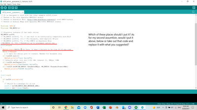
@magnusmagpie I would use the first one above the void setup(). Make sure you un-comment out the line, just remove the // in front of the RH-NRF24 (8, 53);
If that doesn't work then I might try commenting out the RH_NRF24 nrf24; 4 lines above it.
Lot of trial and error sometimes , but great when it finally works.
Arlo
Thanks. I actually figured it out.
I have moved on to the joystick Demo and I am now struggling to make the server (my Mega) receive the joystick values from my Uno (client, which seems to be working fine). How would I solve this issue assuming that I need to make the code recognize the pins 8 and 53 as I did before?
The code is as follows:
/*
nRF24L01+ Joystick Receiver Demo
nrf24l01-joy-rcv-demo.ino
nRF24L01+ Receiver with Joystick Decode
Use with Joystick Transmitter Demo
DroneBot Workshop 2018
https://dronebotworkshop.com
*/
// Include RadioHead ReliableDatagram & NRF24 Libraries
#include <RHReliableDatagram.h>
#include <RH_NRF24.h>
// Include dependant SPI Library
#include <SPI.h>
// Define addresses for radio channels
#define CLIENT_ADDRESS 1
#define SERVER_ADDRESS 2
// Create an instance of the radio driver
RH_NRF24 RadioDriver;
// Sets the radio driver to NRF24 and the server address to 2
RHReliableDatagram RadioManager(RadioDriver, SERVER_ADDRESS);
// Define a message to return if values received
uint8_t ReturnMessage[] = "JoyStick Data Received";
// Define the Message Buffer
uint8_t buf[RH_NRF24_MAX_MESSAGE_LEN];
void setup()
{
// Setup Serial Monitor
Serial.begin(9600);
// Initialize RadioManager with defaults - 2.402 GHz (channel 2), 2Mbps, 0dBm
if (!RadioManager.init())
Serial.println("init failed");
}
void loop()
{
if (RadioManager.available())
{
// Wait for a message addressed to us from the client
uint8_t len = sizeof(buf);
uint8_t from;
if (RadioManager.recvfromAck(buf, &len, &from))
//Serial Print the values of joystick
{
Serial.print("got request from : 0x");
Serial.print(from, HEX);
Serial.print(": X = ");
Serial.print(buf[0]);
Serial.print(" Y = ");
Serial.print(buf[1]);
Serial.print(" Z = ");
Serial.println(buf[2]);
// Send a reply back to the originator client, check for error
if (!RadioManager.sendtoWait(ReturnMessage, sizeof(ReturnMessage), from))
Serial.println("sendtoWait failed");
}
}
}
@magnusmagpie I assumed you were working with Bill's server sketch before when I suggested you add RH_NRF24 (8, 53); to line 23 below the RH_NRF24 RadioDriver; code.
Arlo

