Hello Community,
This is my first post (apart from the Introduction).
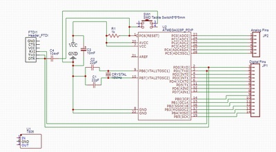
Here is my schematic for "Shrinking your Arduino Projects" Tutorial here - https://dronebotworkshop.com/arduino-uno-atmega328/
The purpose of my trying to get that schematic correct and safe to use (without destroying the ATMEGA 328P) is the fact that I plan to have my UNO free and available for more learning. I have two LED cubes at the moment. Having that schematic fixed, I plan to etch a few of those PCBs and use one of them for learning.
(I could not upload it as an image so I linked it to the image file on my Google Drive).
The Circuit as described in the tutorial works fine. But there seem to be two things that I would like to add -
a. A reset button and
b. A Voltage Regulator.
Some searching got me here - https://www.arduino.cc/en/main/standalone and I managed to add up the Tactile button switch to work as the reset button.
The article mentions the use of 7805 power regulator but then the condition is that I need to provide a power supply that is between 7-16V.
Also, I could not figure out how or where to put that on my circuit/schematic.
So here is the question:
Can I use some other power regulator so that I can use my cell phone power supply (which is 5v 1AMP or some better ones that deliver 3AMPs of 5v)? And if so, where do I put that. Also, if any other components are needed.
Note: I have started learning the basics of electronics very recently and as such, I do not have much idea on how things work (at the moment).
Thank you for reading and helping me start.
Life is exploring and learning
Adding an onboard voltage regulator is not too difficult. I hope the image of this board shows the traces.
I have added 7805T to projects on perma-proto boards too. I use 9v wall adapter power supplies when using the 7805T because they drop a little more than one volt. Lower powered projects I use the L4931 5v regulator. I can connect a 6v wall adapter because these ICs only drop about .6v and can supply about 800mA.
ZoolanderMicro, where small ideas are a big deal
The 78xx series of fixed voltage regulators have three pins; input, ground, output. DC jacks for wall adaptors with 2.1mm connectors are readily available from adafruit or sparkfun. These sites have tutorials on how to use many of the items they sell. Attached is one page of the data sheet that shows the pinout for the TO220 style. I add capacitors on the input and output of the regulator. 10uf might be excessive but works well.
ZoolanderMicro, where small ideas are a big deal
Thanks for the Image. Somehow I now see the place to add my image and so I added it.
As I see, you use two 10uF capacitors' positive ends to feed in and out of the Regulator and probably the C3 capacitor takes in its power from the +ve of the supply. What about the -ve ends of those capacitors.
Also, can you inspect my schematic and let me know if it is okay? Agreed, at the moment, it is without the Voltage regulator.
I ask for confirmation because I have never studied Electronics as a subject and the only few months I have is the past few months. So I always need someone to be my guide. (Thanks for this extra piece of help).
Edit:
As I posted my reply, I saw you added up the PDF for the Datasheet as well. Thanks. I would be using the one on the top right as that is what is locally available and also it is easier for me do add it up on my schematics 🙂
Life is exploring and learning
Also, calculate the dissipated power (Watts) by multiplying the voltage drop (Vin - Vout) by the current. If I am using a 7805 (TO220) with a 9v power supply, Vin - Vout = 4v. If I am pulling 1A through the circuit, that would be 4W of power. Better add a heat sink to that chip!
ZoolanderMicro, where small ideas are a big deal
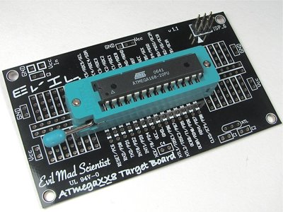
Nice schematic drawing, what program are you using? The ground plane is common to all the components on the board. The capacitors are there to smooth out voltage ripple. There are target boards for a few of the AVR microcontrollers available at EvilMadScientist.
Add a ZIF socket and a 6 pin ISP header and this makes a good target board to program different chips. Add headers and you have a usable controller board. This does assume the use of an external programmer. Good news, you can program your Arduino to be an In System Programmer (ISP).
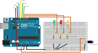
The Arduino as ISP sketch is already in the Arduino IDE. Use M to F jumpers from the Arduino to the 6 pin header of the target board. Use a small piece of heat shrink to hold the F jumper ends together to make attaching and removing easier. The LEDs are there to indicate data transfer, error, and heart beat (blinking light to show it is on and working).
ZoolanderMicro, where small ideas are a big deal
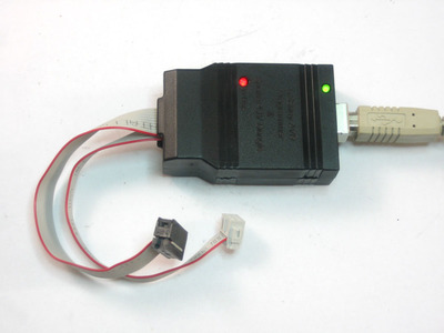
I just noticed that the capacitor in the drawing is installed incorrectly. It should be turned so that the legs are in different traces and connected across the 5v and ground. You might also try using a USBtinyISP, available as a kit.
ZoolanderMicro, where small ideas are a big deal
ZIF sockets fit on breadboards well. Here is a video as an example of an ATtiny4313 chip programmed with an Arduino and an ATtiny2313 target board. I use a ZIF socket to mount the chip on the bread board. That makes it easy to remove and reprogram.
ZoolanderMicro, where small ideas are a big deal
The video below is a brief description of my AVR programming setup. I use a USBtiny programmer connected to a target board with a 20 pin ZIF socket. The board is configured for programming the ATtiny 2313, 4313 series, and with the addition of a jumper wire, the ATtiny 25, 45, 85 series microcontrollers. My laptop is running the driver software for the programmer (connected via USB) and the Arduino IDE to compose, compile, and upload to the target chip.
ZoolanderMicro, where small ideas are a big deal
Nice schematic drawing, what program are you using?
I used EasyEDA - this is available online as a platform as well as a downloadable program. However, there is an issue with it - many a times (for instance with the ATMEGA I used) there are no footprints and as such, it will not translate the schematic to a PCB design/layout. And I have still not been able to figure out how to replace a component (with another) in such a situation. So I have to redo most of the connections for the component in such a case.
Someone did recommend me using Fritzing - but they need a donation to download. I even considered Eagle or KiCad but I found Eagle confusing and KiCad a very big download - I am just someone who has just started, etched only one PCB and barely am in need of these (more so as I etch at home using normal Copper clad boards with Ferric Chloride - and I know it is not a great idea to even attempt bigger boards forget the dual sided ones).
I just noticed that the capacitor in the drawing is installed incorrectly. It should be turned so that the legs are in different traces and connected across the 5v and ground.
Oh. I will look into this for sure. Thanks for mentioning this. I might save one of those ATMEGA-328 chips.
Life is exploring and learning
I am using EagleCAD, and yes, it is a beast. I have added several additional parts libraries to Eagle. You can add libraries to KiCAD as well. Navigate to their web site ( https://kicad-pcb.org/) and click on the Libraries drop down menu. You can choose from several KiCAD or third party libraries to add. The Digi-Key library probably has a full complement of ICs and microcontrollers. I find the SparkFun library useful in Eagle. I just paid (donated) for an updated version of Fritzing. I don't use it for circuit design, but it is great for creating illustrations of circuits like the one that shows using an Arduino as an ISP. There are additional, contributed parts bins (libraries) available for Fritzing too.
ZoolanderMicro, where small ideas are a big deal
I just looked at the EasyEDA web site, and I see what you mean. There doesn't seem to be the same level of support or contributions from major parts distributors as with Eagle or KiCAD. It seems to be community driven support and contributions only. Fritzing has their Fritzing Fab feature for PCB manufacturing. This links to Aisler.net. I have been submitting my board designs to Aisler for prototyping. They are fairly reasonable in price, and they make it easy for hobbyists (like me). Etching your own boards can be fun too.
ZoolanderMicro, where small ideas are a big deal
I just paid (donated) for an updated version of Fritzing. I don't use it for circuit design, but it is great for creating illustrations of circuits like the one that shows using an Arduino as an ISP. There are additional, contributed parts bins (libraries) available for Fritzing too.
True, the only reason they are still being used is their "Breadboard" feature (I came to know of this on forums and some of the images on the blog posts also mention "Fritzing" on their breadboard images. But I wanted to use it because - it was said to be free, and I would be rarely using the circuit designs.
I just looked at the EasyEDA web site, and I see what you mean. There doesn't seem to be the same level of support or contributions from major parts distributors as with Eagle or KiCAD.
EasyEDA is a Chinese company (I think because of their association with their PCB Makers). And they are mostly in use by people (in Asian context) who can get cheaper and quicker delivery of their Manufactured PCBs. (There are many of videos on youtube even by Indians, who endorse and use their services). And one of those videos got me there. I saw the Schematic and the PCB conversion part is free to use. So I got started using it and did my schematic (above) on it. I still have to work on that to get the issue with the Capacitor fixed.
As we are discussing this, the local electronic spares store said that as I am not going to power up my circuit with anything beyond the normal 5v phone chargers, I can skip the Voltage Regulator section and also, I can use the FTDI to load programs onto my chips using a breadboard - and in such a scenario, I can get rid of the FTDI part as well.
The reason I asked him about it is - I only want my ATMEGA chip to run the codes on them - mostly to control the LED Cubes I have and a new project that I plan to do - using RTC clock, Pixel LEDs (10 LEDs at a time) and Internet Access.
Any ideas?
Life is exploring and learning
I want to make an LED cube. I just bought some shift registers to try. DroneBotWorkshop has a good video on shift registers. I'm going to follow along with the video and breadboard the demonstrated circuits. Currently, I am making a coil gun, one of the projects in Simon Monk's book '15 Dangerously Mad Projects for the Evil Genius'. The projects are not really dangerous, and the coil gun is pretty harmless. I am using four 10,000uf capacitors and four 9 volt batteries in series. That's 40,000uf at 36V that will charge a magnet coil and spit a BB out a tube (perhaps across the room). Maybe not that impressive, but it's going to look awesome. I have been making component layout drawings on paper because I still don't know enough about AutoCAD. Learning to use that piece of software might be a steep learning curve. Sometimes low tech is better.
ZoolanderMicro, where small ideas are a big deal
If you can prototype it with an Arduino, you can make it with a free standing microcontroller on a circuit board. Have you ever used a perma-proto board? They are laid out similar to a bread board, but you solder the components. If you can bread board it, you can transfer it to a perma-proto board. Adafruit has them in three different lengths. I had posted a few AVR pinout charts in another topic thread. I will post the ones for the ATmegaXX8 and the ATtinyX4 / ATtinyX5 chips.
You may need to install additional board libraries in the Arduino IDE to program any of the ATtiny series chips. I use the ATtinyCore library developed by Spence Konde. It is also available for download from GitHub ( https://github.com/spencekonde).
ZoolanderMicro, where small ideas are a big deal


