https://www.alibaba.com/product-detail/8-pole-3-throw-electronic-slide_431289779.html
That would certainly be the quickest way to go, and also guarantee that no extra power would be required. This would allow for a hub that has 3 SD cards. That's good enough. I'll probably go with that since it's so simple.
I was actually thinking about using IC switches, something like a 74HC4066. And then enabling those with a physical switch. This would be far more complicated, but it would also allow for building larger capacity hubs.
I think I'll definitely go for the simpler version for the prototype. Although a min order is 5000 pcs. If they are 30 cents a piece that would be,... wait for me to rack my brain,... $1500.00? Is that right? If I get them for 2 cents a piece that would be,... still racking my brain,.... $100. The $100 for 5000 switches wouldn't be bad if I get into selling the hubs. I'll have to look into that one. It's not clear how much they cost.
I know I can get 74CH4066 in large quantities really cheap in either DIP or SOP. The only question there is whether I can run the 74CH4066 chips off the existing SD cable?
It looks like I should be able to. Their Vdd specs are anywhere from 2 to 10v. So they should run on 3.3v.

I'd need to have two of these for each SD card. Then use a physical switch to chose which ones are on and which ones are off.
That wouldn't be too bad.
So far the parts list would be:
- (1) SD cable extender
- (4) SD card sockets SMD
- (8) 74HC4066 switches SMD
- (1) physical switch to choose which 74HC4066 chips are active.
- (1) PCBway PC board.
- (1) Case
That should do it.
The single switch you linked to would make for a simpler hub to be sure. But if I have to buy 5000 of them we'll have to see how much that's going to cost.
DroneBot Workshop Robotics Engineer
James
I just installed KiCAD on the Jetson Nano and that appears to be running so far. So I'm making lots of progress here. ? This is on the same SD card with Blender. This will be my CAD system on the Jetson Nano.
This way I can back up individual SD cards for each type of system and they will not only include the system but will also include all my installed software. This way I also won't be filling up a single SD card with a bunch of unrelated stuff. This is liking having totally separate computers for each purpose.
I'm also taking Paul McWhorter's 9-axis IMU course, and some other Ardunio topics he covers. I've been doing that on my notebook computer. But I'm thinking of switching that over to the Jetson Nano too on a separate SD card. I might end up moving everything over to the nano. ?
DroneBot Workshop Robotics Engineer
James
I spoke too soon with KiCAD. The schematic editor isn't working properly. As soon as I run the mouse over the schematic editor it leaves a trail of mouse cursors behind it everywhere I go. I'll have to figure out how to resolve this issue. I can't use this editor like this.
DroneBot Workshop Robotics Engineer
James
Ok, I got KiCAD working I THINK!
I had to remove KiCAD version 4 and install KiCAD version 5.1 and now I'm able to place components in the schematic editor. Unfortunately they don't have a 74HC4066 chip in the library so I'll need to create one.
That's ok, at least it isn't messing up with the mouse curson anymore.
See, this is why I want to back up these SD cards after I get everything installed properly. I don't want to have to go through this again should the system fail. I also don't want what I'm doing on the CAD system to be messing up my AI system, or my Kdenlive system. This way if something crashes in a major way on an SD card I won't lose everything at once. ?
I was even thinking of making a separate SD card for KiCAD. I put it on the same one with Blender. Trying to keep all the CAD stuff together. And I'm doing this mainly for the software. I can save actual design files to USB sticks. So the data will be separate from the software systems.
Bill got me started on these little Jetson Nanos and now I'm thinking of using them instead of the notebooks. They actually have a lot of nice features. Being able to boot them up on different SD cards is nice. They don't have battery backup when the power fails though. It is nice when the power goes off and the Notebook computers keep running. ?
Anyway, it looks like I have Blender and KiCad installed. Now we'll have to see how well they actually do over the long haul.
DroneBot Workshop Robotics Engineer
James
I have an IDEA!
This is probably not a good thing. ?
I'm starting to design the SD card hub on KiCad. They actually have the SD card sockets in the parts library. That was nice. I need to create my own switch part. But this is when I got this bright idea. Or maybe not so bright?
I'm thinking that instead of switching a 8 lines on the SD cards, maybe I can get by with just connecting all the data and clock pins together on the same bus? And then only switch the power on to the card I want to use?
I wonder if that would work? Would the other SD cards on the buss mess with the data and clock lines if those cards aren't powered up? I figure it might be worth a shot to give it a try. If it worked that would do away with the need to be switching so many lines.
DroneBot Workshop Robotics Engineer
James
Well, this is a nice project to learn KiCAD with. ?
I had to make my own 74HC4066 schematic symbols because I didn't like the ones that came with KiCAD.
The schematic looks pretty. Not quite finished yet. But I'll bet the PCB is going to be a nightmare to run traces on. They aren't going to be as nice as they look on the schematic. I designed the schematic symbol to make drawing up the schematic easy and neat. But the actual pins on the chips are not lined up next to each other. So the traces are going to be crazy.
Here's the schematic. (not yet fully finished). But it's mostly done. I just need to add a 2-pole 4 position rotary switch to select which 74HC4066 chips will be on.
DroneBot Workshop Robotics Engineer
James
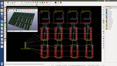
I couldn't go to bed until I dumped the PCB components to see what it looks like:
It's not nearly as bad as I had imagined. I'll know better when I actually start running traces. They won't be like in the schematic because they don't come off the chips the same way they are drawn on the schematic symbols.
But this is looking pretty good so far.
And I'm impressed with this little Jetson Nano. It's running KiCAD without a problem. No hesitations or anything. Just super fast graphics.
So far all is well and good. I've ordered all the parts from Ali Express. Both through-hole and SMD components. I'll make a working model on a bread board first to be sure it actually works. Then if it works I'll do the PCB in SMD and order it from PCBway.
This will be my first order from PCB way and my first real attempt at building an entire SMD project.
This is FUN! ?
Although my real interest in using KiCAD is to build hardware A.I. networks. But that's going to be a while. I have a few other PCB projects I'd like to do in the meantime. But this SD card hub for the Jetson Nano is a nice little practice project.
DroneBot Workshop Robotics Engineer
James
Now I'm back at the schematic again. I just realized that the best practice when creating schematics is to create them in a way that will be very similar to how the traces will need to be laid out on the PCB. For this purpose I drew up yet another new 74HC4066 schematic symbol for the KiCad Schematic Editor. This time the schematic wiring will be more realistic to how the actual chips are laid out. This way I can see from the schematic how the PCB traces will need to be run.
It's a good thing I did this too because I can see where I can make further improvements to the schematic wiring that will make the PCB traces far easier to run. So that will be my next mod to the schematic.
In the meantime this is what I have thus far. I really hope this works out. These will come in handy for both my Jetson Nanos and they might come in handy for use with the Raspberry Pies too. Although I haven't been using the pies as a desktop machine lately.
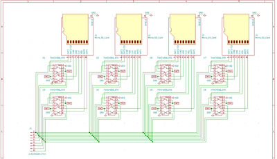
In any case, here's the new schematic. Still more editing to do. I can make it even better than this.
DroneBot Workshop Robotics Engineer
James
I cleaned it up already. I got rid of 16 crossed over traces around the 74HC4066 chips and ended up with only 4 crossed traces at the connector header pins which will be a lot easier to deal with on the PCB layout. This was worth doing to make the PCB layout a lot easier.
I still have 16 more connections to make to the 74HC4066 chips. Plus power and ground. On this schematic they are shown as labels that "magically" jump to far off places. But on the PCB they will need to have real world traces. So I'll need to take those into account as well. I haven't drawn up the 4 position selector switch wiring yet. I'll probably do that on a separate schematic sheet using those "magic" label connectors to connect back to the chips on the first sheet. But like I say, when this gets dumped over to the PCB those extra traces are going to become a real-world issue. So I need to keep that in mind.
This is fun! This will be my first PCB project using KiCAD and SMD components. It will also be my first experience with PCBway. I hope this all works out! It's an experimental idea and it may not even work!
One thing I'm concerned about is whether the 3.3 volts from the Micro SD cable will be capable of driving the 74HC4066 semiconductor switches. I'm actually thinking that I might need to include a step-up buck converter to jump the 3.3 volts up to 5v for the 4066 chips. And then there's the question of whether the 3.3 line on the SD cable can drive all this garbage?
Ideally I'd even like to have four LEDs that indicate which card is active. That's overkill, but it would be a nice touch if I can squeak it in without putting too much burden on the 3.3 volt line. I would like to avoid the need for any additional power connections if possible. This is because I might like to make these as a product and it would be way nicer if you can just plug it into the SD card slot and fly. Most people aren't going to want to have to hook up additional power lines on the GPIO pins or whatever.
DroneBot Workshop Robotics Engineer
James
Yes, Blender does have the dimension notation feature available as a plug-in. Only instead of calling it: "The Invasion of the Annotatians from Hyperspatial Dimensions", they just called it "Measure It"

It's just a simple little add-on:
I am a blender user, and it's getting better every version. The power from blender is in it's vast array of addons. There is another addon I have seen in the past, but I don't remember the name for it. Currently, blender is not the best for CAD work, but I do believe it is on their agenda to incorporate a CAD interface at some stage, but that could be a long way away right now.
I'm only just starting with it right now but it certainly looks promising. I'm working on learning how to draw up a detailed wheel and tire. This is part of my robot design. I'll probably be drawing tires for the next month or two. Not because it's difficult to draw tires, but because I'm also using this as an exercise to learn all the different ways that it can be constructed. I've watched different tutorials on how to draw a tire and I see that people are using many different ways to do it, some better than others.
The other thing I'm currently studying is the Import, Export, Link and Append options. I used to work with Google Sketchup and I got hooked on their "Components" feature. Once you create a component you can add it to your drawing, and then later if you want to modify just that component you only only need to modify the component and it updates everywhere its used in the drawing. I see Blender offers something similar by keeping objects in different files and linking to them. And there appears to be a lot of different options for doing that so lots to learn about that.
Finally I like keeping things on separate layers as well and I see that Blender offers this too, including the ability to have rigging layers as well as animation control layers. That's going to be quite a bit down the road for me, but it's certainly a feature I'm looking forward to learning about. It would be nice to be able to make animations of my robot while I'm designing it. ?
In fact, there will probably be good ideas that come out of trying to animate it on blender that might help me to design better actuators in the real world for the real robot. So it's definitely going to be a very powerful tool to be sure.
DroneBot Workshop Robotics Engineer
James
I love working with 3D in Blender, but as I have many hobbies like, I often stop using it for periods of time, then have to go back and re-learn some things again... same with Electronics, etc... 🙂
Which version did you download?
As of 2.8, Blender now has collections instead of layers, which are far more flexible.
Most of my work on Blender so far has just been modelling and rendering, and I started to learn the python API which is a lot of fun too 🙂
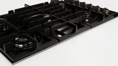
Here's an example of a gas cooktop I modeled and rendered:
I haven't done much by way of rigging and animation, but have been keen to start on it to complement my engineering background - I want to see my designs move! 🙂
Very powerful indeed!
Which version did you download?
I have version 2.79.
I just watched a nice little video on how to animate some things. So I'm excited to try that out.
He's using Blender 2.81 though, so I may not be able to do what he's doing using 2.79.
I might need to upgrade to the latest version before I get too used to the older menus and toolbars.
DroneBot Workshop Robotics Engineer
James
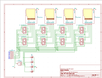
I finished the SD Card Boot Hub. I've decided to call it a "Boot Hub" rather than just a hub. The reason being that only one SD card will be accessible at a time. It's designed specifically for the purpose of being able to boot to different System cards. Although I suppose it could be used on a data SD line too. The only catch is that you could still only access one card at a time. You'd need to physically turn the selector switch to access a different card. In any case I've decided to call it an "SD Card Boot Hub" because it's really designed for to be used as the Boot SD card on SBC's that boot up on an SD card like the Raspberry Pi and Jetson Nano.
In any case, I added the selector switch and it turned out to be way easier than I had first imagined. In fact, it actually made things simpler because I'm using the same Vdd and Vss as the SD cards.
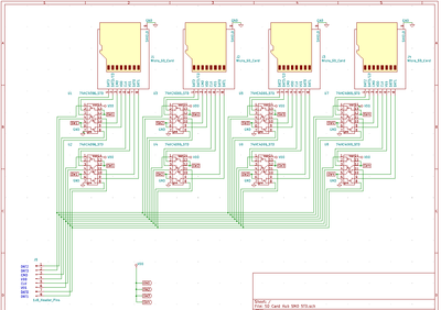
Here's the final schematic: I even added four indicator LEDs to indicate which card is active. Only I just now noticed that I forgot to include current limiting resistors. Oh well, back to the drawing board again. ?
I still don' t know whether this design will even work or not. All it does is physically switch between the SD cards. I don't see why it wouldn't work. The only concern I have is that the 74HC4066 switches might not run on 3.3 volts. If that's the case then I'll need to add a buck converter to the mix to step the 3.3v up to 5v and that could overly complicate things. Another option would be to use 74HCT 4066 which might run on the lower voltage. But they are quite a bit more expensive. Not bad if I'm only building a couple of these for myself. But like I say, if it works I might put these on Etsy or something and see if I can sell them. So I'm trying to keep the cost down. In any case, I've ordered all the parts. They should be here in about a month. Yeah, it's the slow boat from China again. ?
I could make some higher qualities ones using parts from Digi-Key, but if I go that route the finished product would need to reflect those higher prices too. We'll see. I might try both sources for parts and decide which way I want to go later. Maybe even offer too models. One "Made in USA with parts from Digi-key" and the other one "Made in USA with parts from China". ?
Better wait and see it if actually works first.
Now I'm off to design the PCB. I guess I better check the PCBway site first and see what their standard PCB sizes are. May as well work with a standard size to keep the cost down.
DroneBot Workshop Robotics Engineer
James


