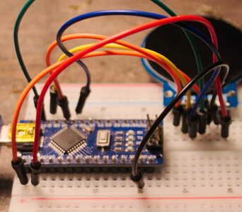
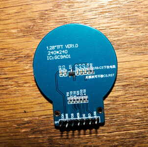
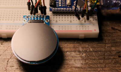
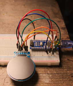
I used an inexpensive 1.28"TFT round display GC9A01. In the photos it is connected to an arduino nano. I used the code from the Waveshare wiki and followed Bill's instructions. The display did not light up. Picture of the back of the module is included. Bill mentioned that the display type I have, uses 3.3 volts so that is what I used.
@richardbr Use one of those power supplies that goes across the breadboard to supply the display, be sure to common the grounds. The reason I say that is in case the board you are using does not have the power needed for the display. Remember Bill used an UNO. Here is amazon.ca link
First computer 1959. Retired from my own computer company 2004.
Hardware - Expert in 1401, and 360, fairly knowledge in PC plus numerous MPU's and MCU's
Major Languages - Machine language, 360 Macro Assembler, Intel Assembler, PL/I and PL1, Pascal, Basic, C plus numerous job control and scripting languages.
Sure you can learn to be a programmer, it will take the same amount of time for me to learn to be a Doctor.
I used a bench power supply and still the display didn't light up. Need to find the documentation for this module if it exists. Thanks for your help.
@richardbr This is all you need https://dronebotworkshop.com/gc9a01/
First computer 1959. Retired from my own computer company 2004.
Hardware - Expert in 1401, and 360, fairly knowledge in PC plus numerous MPU's and MCU's
Major Languages - Machine language, 360 Macro Assembler, Intel Assembler, PL/I and PL1, Pascal, Basic, C plus numerous job control and scripting languages.
Sure you can learn to be a programmer, it will take the same amount of time for me to learn to be a Doctor.
Hello!
First post - I'm Bob W9RAN, ham radio nut since teen years and general electronics tinkerer and builder. I found this forum after becoming interested in the GC9A01 round TFT displays. Most of my software activities center around radio somehow and I thought these displays have the potential to be used as interesting user interfaces, as we humans are already programmed to turn round things 😉
However I've had zero success in getting the examples to work. With one exception - I was able to get the Waveshare static display to come up using an Arduino UNO which at least proves the display is functioning right, but no luck at all with the ESP32. In fact I've tried a different project from another site with the same results - nada.
The displays I have are not from Waveshare, but have 8-sided PCBs and a slightly different pin sequence, but are GC9A01s. I am using the ESP32-WROOM-32D dev board, which appears to be identical with the unmarked one showing in the fritzing diagram. I've edited and double-checked the changes to the User_Setup.h file which tells the library which pins to use.
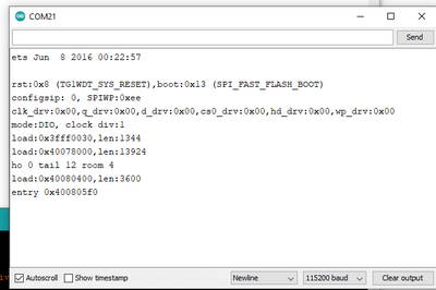
I'm trying to run the Colour_test.ino sketch as suggested in the article. The code compiles without error but after uploading the display remains blank. I can see around the edge that the backlight is lit. The problem is, something is blowing up the ESP32 causing its bootloader to spew out a (fairly incomprehensible) dump:
The sketch does not even enable the serial monitor so this is being generated from the bootloader, kernel, or something at a lower level and obviously it is not happy. I'm out of ideas to try, and since this was presented as a proven application I'm hoping I'm just overlooking something. Any suggestions will be appreciated, thanks!
Bob
@w9ran The 'incomprehensible' message is normal. It is just basic info about the esp32. I will be out of commission pretty much until the end of June or even later, but I can tell you I recall Bill warning us that the clone boards would be a challenge. I have a few on my wish list but I have not ordered them yet. Perhaps you can share a picture of the module so we can also see what is there, and also post the contents of the User_Setup.h and perhaps the documentation that tells you how to modify that file.
First computer 1959. Retired from my own computer company 2004.
Hardware - Expert in 1401, and 360, fairly knowledge in PC plus numerous MPU's and MCU's
Major Languages - Machine language, 360 Macro Assembler, Intel Assembler, PL/I and PL1, Pascal, Basic, C plus numerous job control and scripting languages.
Sure you can learn to be a programmer, it will take the same amount of time for me to learn to be a Doctor.
@richardbr Are you still around? I am very interested in using a few of these displays. I think I see an issue around the 'clones' but need an open line of communications to trouble shoot. Either post back if you are interested or send me a Private Message (you may have to get your post count up to 10 before you can do that, though)
First computer 1959. Retired from my own computer company 2004.
Hardware - Expert in 1401, and 360, fairly knowledge in PC plus numerous MPU's and MCU's
Major Languages - Machine language, 360 Macro Assembler, Intel Assembler, PL/I and PL1, Pascal, Basic, C plus numerous job control and scripting languages.
Sure you can learn to be a programmer, it will take the same amount of time for me to learn to be a Doctor.
@zander Hi Ron,
I think these are all SPI displays, some just incorrectly use I2C designation "SDA" for data input. The clock pin is correctly labelled SCK rather than SCL (as for I2c) so it's a bit of both. I just made sure the connect the pins to match the signal definition.
Does your reference to "clones" refer to clones of the GC9A01 display or ESP32 clones? I've only done one other project with the ESP32 but there are a number of different configurations and I haven't yet found a good description of what the differences are. In addition to the MCU the ESP32-WROOM-32D dev board also contains a 4 MB SPI Flash IC, a 40 MHz Crystal Oscillator, PCB Antenna and some discrete passive components and all GPIO lines (some of which are used by the serial Flash). My boards have 19 pins on each side, 38 total, but as long as the proper GPIO pins are used I wouldn't think that would matter.
Bob
@w9ran I was referring to the GC9A01. Yes, I thought I corrected myself on the I2C comment, they are as you say SPI.
As far as esp32 clones, the esp32 part is a small part of the board. Most of the board is IO and other goodies. As far as the differences, the spec sheet is useful, and another decent source is the Arduino IDE. Check out all the settings under Tools you can modify (see pic) other boards will have more or less changeable options. I have esp32 boards with 38 pins, 36 pins, even fewer pins, some wider than others etc. If I ever run into an issue caused by the specific boards I have I guess I will have to learn how to pick a better-suited board, but at the moment my random collection does everything I need.
First computer 1959. Retired from my own computer company 2004.
Hardware - Expert in 1401, and 360, fairly knowledge in PC plus numerous MPU's and MCU's
Major Languages - Machine language, 360 Macro Assembler, Intel Assembler, PL/I and PL1, Pascal, Basic, C plus numerous job control and scripting languages.
Sure you can learn to be a programmer, it will take the same amount of time for me to learn to be a Doctor.
post the contents of the User_Setup.h and perhaps the documentation that tells you how to modify that file.
Yes, that is a good suggestion - I suspect that you might need different settings in User_Setup.h for that display.
I think these are all SPI displays, some just incorrectly use I2C designation "SDA" for data input. The clock pin is correctly labelled SCK rather than SCL (as for I2c) so it's a bit of both
You are correct, they are mislabeled SPI connections!
I've only done one other project with the ESP32 but there are a number of different configurations and I haven't yet found a good description of what the differences are.
Sara Santos at Maker Advisor has a post on selecting ESP32 boards. The Random Nerd Tutorials site she and Rui run is probably the best ESP32 resource on the web.
Again, please post the User_Setup.h edits you made, as I suspect that could be the issue.
😎
Bill
"Never trust a computer you can’t throw out a window." — Steve Wozniak
The edits basically comment in/out the display in use since the library was written to support a variety of displays, and then assigning the pins for SPI functions. Of course failing to enable some needed function could be have the same effect as incorrectly specifying something, so I'll attach the whole thing. Thanks to anyone who is willing to take a look, as I can't see anything wrong with it. Since the backlight pin is tied high to turn it on, there is no pin assigned to it.
Bob
@w9ran Have you got any of the Waveshare or Adafruit sketches to work? If not, try a second GC9A01 as the first may be DOA.
First computer 1959. Retired from my own computer company 2004.
Hardware - Expert in 1401, and 360, fairly knowledge in PC plus numerous MPU's and MCU's
Major Languages - Machine language, 360 Macro Assembler, Intel Assembler, PL/I and PL1, Pascal, Basic, C plus numerous job control and scripting languages.
Sure you can learn to be a programmer, it will take the same amount of time for me to learn to be a Doctor.
@zander I found the Dronebot forum while searching for information about using the Adafruit library, and while there is one example provided for the Adafruit GC9A01 display I haven't been able to find the SPI wiring for it, just the sketch on github: https://github.com/PaintYourDragon/Adafruit_GC9A01A. The header says Adafruit does not provide these displays or support for them.
Bob
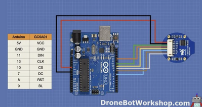
@w9ran Yes, that is what Bill used. The comment re non-support is a common language when code is free. Wiring diagram is as Bill supplied. It may be a bad module, the normal testing procedure is to plug in a second unit. If it also does not work, the issue is most likely in your wiring or code, if the second unit works, then the first is a broken unit.
First computer 1959. Retired from my own computer company 2004.
Hardware - Expert in 1401, and 360, fairly knowledge in PC plus numerous MPU's and MCU's
Major Languages - Machine language, 360 Macro Assembler, Intel Assembler, PL/I and PL1, Pascal, Basic, C plus numerous job control and scripting languages.
Sure you can learn to be a programmer, it will take the same amount of time for me to learn to be a Doctor.
Thank you for this video. I made it work with a raspberry pi pico!
#define GC9A01_DRIVER
// For ESP32 Dev board (only tested with GC9A01 display)
// The hardware SPI can be mapped to any pins

#define TFT_MOSI 19 // In some display driver board, it might be written as "SDA" and so on.
#define TFT_SCLK 18
#define TFT_CS   22 // Chip select control pin
#define TFT_DC   21  // Data Command control pin
#define TFT_RST  20  // Reset pin (could connect to Arduino RESET pin)
#define TFT_BL   26  // LED back-light

