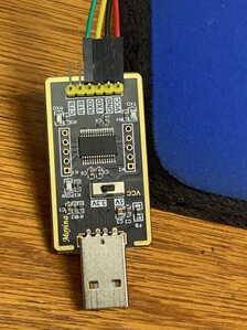
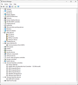
I setup the ESP32 Cam one or two years ago. Since I have a new computer - Asus mother board windows 11 Pro. Now when I try to upload the program through the FTDI adaptor, I get an error message saying it couldn't connect to serial port com1. The FTDI adaptor I have has a USB plug that plugs into my computer. I have no idea which USB is COM1. Also when the FTDI adaptor is plugged into any USB port the transmit and receive light is on all the time and the chip gets quite warm. The adaptor has FT232 printed on it.
@ddaved I do a lot of work with the ESP32CAM but I use a Mac. What I would try is to connect the ESP32CAM to the computer first , then fire up the IDE and load the sketch, then if you don't connect automatically, use the menu to select the port, there is a good chance it will be properly listed. I also don't need the FTDI anymore as I use the ESP32-MB board that supplies a USB connection as well as a few other benefits.
Here is a link to amazon.ca, change the country to match yours https://amz.run/63ux
First computer 1959. Retired from my own computer company 2004.
Hardware - Expert in 1401, and 360, fairly knowledge in PC plus numerous MPU's and MCU's
Major Languages - Machine language, 360 Macro Assembler, Intel Assembler, PL/I and PL1, Pascal, Basic, C plus numerous job control and scripting languages.
Sure you can learn to be a programmer, it will take the same amount of time for me to learn to be a Doctor.
Thanks, Ron for the quick reply. I connected the FTDI to the computer before loading the Arduino IDE 2.0.0. Same error so I checked the port listed in tools. There is only one port listed - COM1.
I should mention if I remove the ESP32 CAM from the FTDI only the power light is lit amber. But when the ESP32 CAM is connected the green and red leds light up when the FTDI gets plugged in.
@ddaved Sorry, that's all I got since I am Mac not Win and USB not FTDI. Somebody else will jump in I am sure.
First computer 1959. Retired from my own computer company 2004.
Hardware - Expert in 1401, and 360, fairly knowledge in PC plus numerous MPU's and MCU's
Major Languages - Machine language, 360 Macro Assembler, Intel Assembler, PL/I and PL1, Pascal, Basic, C plus numerous job control and scripting languages.
Sure you can learn to be a programmer, it will take the same amount of time for me to learn to be a Doctor.
Hi @ddaved,
I am still on Win 10 and Linux, but assuming Win 11 is keeping to Win 10 and before traditions:
Is the FTDI adapter showing up in the Device Manager, and does it appear to have the correct driver or is it complaining?
If it is complaining, first try deleting ("uninstall") the adapter entry, and get Windows to search for devices. Sometimes it will automatically find the right driver. If this fails, then a Google search for a driver is needed.
-------
When the adapter is showing up, and is not complaining (i.e. not showing a "!" mark or similar), then a trick I have used in the ancient past to ensure Windows and the adapter are on good speaking terms with each other, is:
Link TxD and RxD pins of the adapter output. Use one of the terminal programs like TeraTerm, to show that what you type goes out of the TxD pin and reflects back into RxD pin, and displays on the screen.
I have just fired up TeraTerm with my Arduino clone card plugged in, and on the Serial port set up page it shows "Device Friendly Name: USB Serial Port (COM4)" in the status window ... I would guess you would get something similar.
Do a check that it only works when TxD and RxD pins are linked, since terminal programs can usually be configured to show the key presses locally.
--------
When you have this working, hopefully Arduino IDE will also find it .. presently I am using Linux with Arduino 2.0, which shows the same Mega2560 port as "/dev/ttyUSB0".
Both Windows and Lnux also show a different port, "Com1" and "/dev/ttyS0", which are NOT the USB port ... and may not even physically exist .. ignore them if they show up ...
Windows tries to treat USB ports like 'standard' COM ports, and sometimes labels them as COMx where x=1,2,3, 4... , but there is usually at least one place where it can be identified as a USB virtual COM
--------
Hope this helps. Dave
Before your Arduino IDE can recognise ESP32 ports (for camera or otherwise), etc... you need to download and install the Windows drivers for your ESP32*
Have you done that as a bare minimum?
Cheers
Hi @frogandtoad and @ddaved,
Sorry, I am a little confused by your (@frogandtoad) reply to me .... sorry if my explanation was that confusing.
- It wasn't my question ... I was trying to provide an answer ....
- With ESP32-CAM board and others, the interface is a serial one, not USB ... like the old skool RS232 but with inverted logic level voltage signalling ... so there is no ESP32* driver as such .. the driver is a rather more generic USB to serial driver ... and that driver depends on the chip on the USB to serial card. It is often referred to as an "FTDI adapter".
------------------------
Of course, I agree that an appropriate Windows (or Linux or (maybe?)Apple) driver must be successfully installed first ... that is what I tried to explain in my answer.
Unfortunately, Windows often tries to install a driver, but fails ... hence the need to look in the Device Manager. Linux can have similar problems - I don't know about Apple.
------------
Unfortunately "FTDI adapter" is something of misnomer. "FTDI" is small chip design company who produced some useful for chips for doing this USB to serial conversion, and published the Windows drivers to match. Unfortunately for FTDI, their silicon was heavily cloned, not always accurately, and they lost out financially.
In addition, FTDI and others have produced many variant devices on the same theme, many of which need slightly different drivers. Of course, the clone manufacturers rarely provide adequate driver support, so finding an appropriate driver can be a bit of a lottery.
However, the driver needed is one of USB to serial ... not ESP32 specific.
Labelling is a bit varied, but something like "USB Serial" or "USB to TTL" or "ttyUSB0", as well as FTDI, are often seen.
I hope that clarifies a couple of points.
Best wishes, Dave
Hi @ddaved,
It looks like you might have more than 1 issue with your PC ... and I am not sure your PC has even noticed your FTDI adapter. So let's take it a step at a time.
-----------------
As a comparison, I have just plugged my FTDI adapter (which superficially looks similar to yours, but there are so many clones on the market, it may be completely different) into the PC I am using to write this note ... I DO NOT use this machine for Arduino stuff, so I haven't put any drivers on it.
I was expecting it to spot the adapter, but not recognise it ...
However, it appears to have found a driver, and shows it in the Control Panel
I confess to being a bit surprised, as when I first tried the same thing a few hours ago it came up as a USB Serial port, but with an exclaimation mark in a triangle, showing it had seen it was plugged in, but didn't have a matching driver ...
So that is an example of what you are looking to achieve!
Until you have something similar, Arduino IDE will not have anything to offer.
---------
Looking at your Control Panel, you have no less than 4 objects with an exclaimation mark
-----------------
Clearly the PCI and SM Bus controller objects are a different problem ... whilst they may be harmless, it might be a good idea to do some Googling for a fix ... the PC I am using to write this message .. an elderly HP laptop acquired something similar after I did a complete Win 10 install a few months ago ... and I found a driver update on the HP support forum ... so longer term, I suggest you find your PC model number and Google to see if there is a fix. But sadly, I doubt if that will fix your FTDI adapter problem..
--------------------
So that leaves "Unknown Device" ... this could be your FTDI adapter or it could be related to the other three.
There is also COM1 port ... but I doubt if that is the one you need, but apply the following tests to it as well the Unknown Device, at least until you discover which one is related to the adapter.
You need to do some detective work ... start with unplugging the adapter .. does the control panel item go away? .. and does it reappear when you plug it in?
Usually Control Panel will update automatically, but for the devices mentioned, you can manually delete an entry by right clicking on it and choosing "Uninstall"
And recover it by going to "Action" on the menu bar, and choose "Scan for Hardware changes", whereupon any connected hardware will reinstate the entry.
(Beware of uninstalling more 'critical' computer items. I have never seen a problem that can't be resolved but uninstalling the video card (say) can take a little untangling!)
Also, try right-clicking on the item and going through "Properties" to find any clues as to what it is.
See
https://www.howtogeek.com/193798/how-to-find-drivers-for-unknown-devices-in-the-device-manager/
for some more guidance on how to do this and what to look for.
If you can find some 'magic' Hardware IDs you have something else to Google for drivers, etc.
Good luck ... it can be frustrating but there is usually answer ... somewhere!
Best wishes, Dave
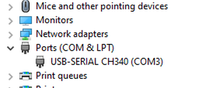
Now we're getting somewhere. This explanation is going to be stupid simple. I watched the Device manager while plugging in a Memory Stick. The computer beeped. When I plugged in the FTDI with ESP32 Cam attached, there was no beep. So I disconnected the ESP32 CAM and plugged the FTDI board by itself - computer beeped and Device Manager displayed USB Serial Port (COM3). For further testing, I compiled the sketch and tried to upload it. I watched the FTDI board and saw the red transmit led blink. I think the ESP32 Camera board is NFG (Not Functioning Good) or it was hooked up wrong. I will not research that part of the problem. I am quite sure the computer is talking to the FTDI Board.
Will report the results.
Boy Oh Boy, I thank you for the help.
I will NOW research that problem - Not NOT Research.
Stupid 83 year old!
Hi @ddaved,
Good to see you have made one step forward.
-------------------------------
I assume you have carefully watched Bill's (@dronebot-workshop) excellent videos on ESP32 (introduction to) and ESP32-CAM ... if not, grab a mug or two of your favourite beverage and enjoy them!!
---------------------
Looking more carefully at your photo, I see your FTDI card is a bit different from mine.
Beware of a confusion with all FTDI cards..
For the ESP32 cards, the processor is 3.3V ... so the logic pins (TxD and RxD) must (in theory**) be using 0-3.3V levels.
Power to the ESP32 has two options:
- 5V to the 5V pin ... and let the regulator on the ESP32 convert it to 3.3V
- 3.3V to the 3.3V pin ... directly powering the processor
On some FTDI boards there are two power voltage output pins
- 5V direct from the USB input
- 3.3V from the regulator on the FTDI card
In the photo I can see one 3.3V/5V switch, and one VCC power output pin. So I don't know if switch is changing:
- Logic level voltages only
- VCC power output voltage only
- Both logic and VCC voltages
Perhaps you have some documentation to verify?
If not, then a voltmeter can be used to monitor the outputs from the FTDI card, when the ESP is DISCONNECTED.
- VCC pin to GND pin ... look for 3.3V or 5V. Does the switch position affect it?
- TxD pin to Gnd pin ... look for 3.3V or 5V. Does the switch position affect it?
Note, it is possible the TxD pin will show about 0V .. Mine shows 3.3V, and I think that should be the 'no messsages to transmit' value, but it might not apply to your card.
----------
With that information make sure your FTDI card TXD / RxD level is set for 3.3V operation, and connect FTDI VCC output to either the ESP 3.3V or ESP 5V, according to which voltage the FTDI card is outputting.
If you think you have a broken ESP card, you might wish to check the voltages when the cards are all connected ... they should be very close to the same values that you saw with just the FTDI card.
-----------
After that .... I wish you luck !!
-----------
NB I wrote (in theory**) above .. one of the members on the forum reported his card would only work with the FTDI card logic level set to 5V ... obviously, I accept this was an honest personal observation ... and I have seen a 2nd report of the same on the Web. I suspect there is something 'weird' a few of the FTDI cards in circulation, but I can't verify it.
I can confirm, the only 'safe' logic level for ESP cards is 3.3V ... if out of desparation you find yours works at 5V, 'good luck' , but 'magic smoke' is the more likely result. I am not recommending it!!!
-------------
Best wishes, Dave
(NB if you spot a typo just after hitting ADD REPLY, you may find an "Edit" button is available to correct the mistake ... I am not sure how long it stays available, but it is usually long enough to have yet another read through!!!
Also the Preview button below the edit window means you can see what it looks like before hitting ADD REPLY.)
@ddaved Which driver did you download and from where?
First computer 1959. Retired from my own computer company 2004.
Hardware - Expert in 1401, and 360, fairly knowledge in PC plus numerous MPU's and MCU's
Major Languages - Machine language, 360 Macro Assembler, Intel Assembler, PL/I and PL1, Pascal, Basic, C plus numerous job control and scripting languages.
Sure you can learn to be a programmer, it will take the same amount of time for me to learn to be a Doctor.
Hi @frogandtoad and @ddaved,
Sorry, I am a little confused by your (@frogandtoad) reply to me .... sorry if my explanation was that confusing.
- It wasn't my question ... I was trying to provide an answer ....
My apologies!
With two of you dave**'s posting, I guess I replied to the wrong one 🙂
Cheers
Thanks for the help. The 3v/5v switch switches the VCC and TxD voltages from 3v to 5v.
I did not download any drivers. The reason my Serial Port Com3 was not showing up was because I had the strap for programming from U00 to Ground. When plugging the camera and FTDI in properly strapped, the computer acknowledged by beeping.
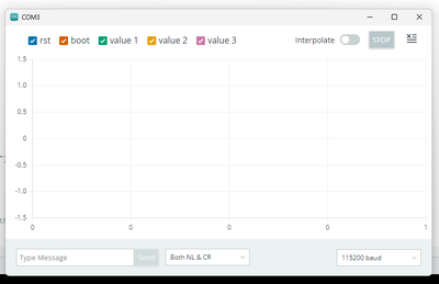
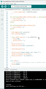
Now, after the program gets uploaded and "Hard reset via RTS pin" is displayed, in the video a screen display with /dev/tty/usb0 is displayed. Nothing is automatically displayed on my screen. I found an icon at the top right of the screen labeled serial plotter. When I select it and then press the reset button on the camera board, I get the display in the attached picture.
The serial display does not show starting operation like Bill's video shows.
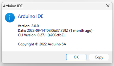
Also, I should comment, the IDE I am using does not have a colored vertical menu as in Bill's video. It is "Arduino IDE 2.0.0" - see attach picture 02.
I have screenshot of the IDE as picture 03. These pictures are showing up very small on my screen, let me know if you can't see them.
Sorry I'm lost again.
ddaved
YEA! - The edit works ! !

