Expand your Arduino with shift registers! Today I will show you how to use the 74HC595 and 74HC165 to increase your Arduino's inputs and outputs so we can flash a bunch of LEDs.
Article with all the code: https://dbot.ws/shift
Shift registers are sequential logic circuits that can be used to convert between serial and parallel data. Really exciting stuff, right?
Well although these fundamental building blocks may not seem that thrilling, they can be really useful in expanding the number of digital outputs and inputs on Arduino and other microcontrollers.
Today we will work with two common 8-bit shift registers, the 74HC595 and 74HC165.
We will use the 74HC595 to drive eight LEDs with just a few connections. By cascading these chips we can drive a lot more LEDs. We will also use the 74HC595 to drive a 7-segment LED display.
After that we will hook up eight push buttons to a 74HC165, reading them all using just a few I/O lines on our Arduino.
And finally, we’ll put both chips together and build a really fun LED light sequencer with eight different flashing patterns.
Here is a breakdown of this extensive coverage of shift registers with the Arduino:
00:00 - Introduction
03:03- How Shift Registers Work
07:32 - More outputs with the 74HC595
15:22 - Driving a 7-Segment Display
21:49- Extra inputs with the 74HC165
29:46 - 74HC595 & 74HC165 Together
34:30 - Custom Light Sequencer
If you’d like to get the code I used to make all this magic happen just visit the DroneBot Workshop website where you'll find a full article to accompany this video at https://dbot.ws/shift.
"Never trust a computer you can’t throw out a window." — Steve Wozniak
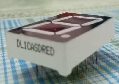
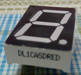
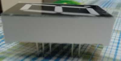
The seven segmented LED display, which you showed in the video had 10 pins. But my seven segmented display has 11 pins. Also, the pins are arranged on the left and right sides of the display and not on the top and bottom side, as shown in the video. I also can't understand, whether it's common anode or common cathode. Model no. DL1CASDRED
Please help 🙏
That model(?) number produces no results are you sure it is correct. Who is the manufacturer?
SteveG
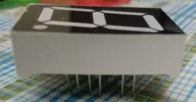
I am sending another image later. But, it's something like this:-
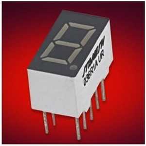
But, it has 11 pins instead of 10. The model no is not correct in this image. But look at the alignment of the pins.
Yes I had the same thought.
I would probably just experiment trying two pins at a time and noting the result to work out where the common cathode or common anode are.
Make sure your probe has an appropriate inline resistor to limit the current for these LEDS and whatever voltage you use.
Still not finding anything that has a model/part number as shown on your part.
The part number @robotbuilder reference is a common anode part, while the common cathode part number for the same device is DL1-CRB instead of DL1-ARB. Note the one letter difference. "A" for common Anode and "C" for common Cathode.
Where did you get your part? Maybe they have the answer you need. And the pinouts for similar parts I have found always seem to have pins 4, 5, and 12 "missing" so on a 14 pin package that would mean 11 pins remaining. The "CA" in your part number leads me to believe your part may be a common Anode device. The diagram on LEFT in the pic included below. The diagram on the right is a common Cathode device.
Notice this diagram mentions that pins 4, 5, and 12 have no pin. And that pin 3 and 14 are common to each other. Pins 6 and 9 are the decimal points, with 6 being the left decimal point and 9 being the right decimal point. Since your device has only one decimal point, I would assume pin 6 on your device doesn't do anything.
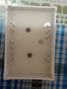
On the photo of the bottom of your device, that I see you posted as I began my long winded testing procedure presented here, pin 1 is the pin in the upper right corner and pin 14 is in the upper left corner. Using that numbering sequence you can see that pins 4, 5, and 12 are missing,
To test this device I would try the following (Please read all steps before proceeding):
- Connect 5V to one lead of a 470 ohm resistor.
- Connect the other lead of the resistor to pin 3 or 14 (I'd use 14 since it is on a corner).
- Then one at a time ground the remaining pins on the device. (stay AWAY from pin 3).
- I'd start with pin 9 to see if the decimal point lights up. (try pin 6 just to see if anything happens)
- Then try the remaining pins, 1, 2, 7, 8, 10, 11, and 13. (hopefully each segment individually lights)
- If nothings lights, then maybe the assumption that this was a common Anode device was wrong and we need to try as a common cathode.
- To wire as a common Cathode, attach the lead on the 470 ohm resistor that went to 5V to ground instead.
- Then retest but momentarily touching a 5V source to the pins in the order in steps 4 and 5 above.
Let us know how you make out!
Please also note that while testing we used just one resistor. To use this in an application you would need a resistor on all but pins 3 and 14. Although if pin 6 of your device does nothing, you won't need a connection to anything.
SteveG
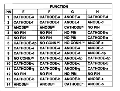
Hi, just looked for 7 Segment Display from HP and found a table for different versions:
May be it helps. I would use 5 v a Diode and a 470 Ohm in serial then you can try any combination with no risc.
I am speechless. I genuinely don't have any words, how to thank you. 😀
The thing went like clockwork. IT WORKED!!!!!!
I just shared a few pictures of my display, and with just that, you could predict how to get this stuff working. When I couldn't find anything useful in Google, you were my benefactor.
THANK YOU SO VERY MUCH!!!!!!!!
Glad that helped! But I'm curious, was it a common Anode device as first suspected, or was it a common Cathode device? And what about the decimal point? Was pin 9 the decimal point and pin 6 did nothing, like it was not connected to anything?
SteveG

